NCP102
NCP102 is Low Dropout Linear Regulator Controller manufactured by onsemi.
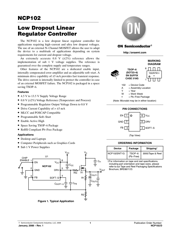
Low Dropout Linear Regulator Controller
The NCP102 is a low dropout linear regulator controller for applications requiring high-current and ultra low dropout voltages. The use of an external N-Channel MOSFET allows the user to adapt the device to a multitude of applications depending on system requirements for current and dropout voltage.
An extremely accurate 0.8 V (±2%) reference allows the implementation of sub 1 V voltage supplies. The reference is guaranteed over the plete supply and temperature ranges.
Other Features of the NCP102 are a dedicated enable input, internally pensated error amplifier and an adjustable soft-start. A minimum drive capability of ±5 m A provides fast transient response. The drive current is internally limited to protect the controller in case of an external MOSFET failure. The NCP102 is packaged in a space saving TSOP-6.
Features
- ă4.5 V to 13.5 V Supply Voltage Range
- ă0.8 V (±2%) Voltage Reference (Temperature and Process)
- ăProgrammable Regulator Output Voltage Down to 0.8 V
- ăDrive Current Capability of > ±5Ăm A
- ăMLCC and POSCAP patible
- ăProgrammable Soft-Start
- ăEnable Active High
- ăSpace Saving TSOP-6 Package
- ăRo HS pliant Pb-Free Package http://onsemi.
MARKING DIAGRAM
TSOP-6
(SOT23-6)
102AYW G
SN SUFFIX
CASE 318G
102 = Device Code A = Assembly Location Y = Year W = Work Week G = Pb-Free Package
(Note: Microdot may be in either location)
PIN CONNECTIONS
EN 1 GND 2
6 VCC 5 DRV
FB 3
4 SOFT-S
Applications
- ăDesktop and Laptops
- ăputer Peripherals such as Graphics...