NCP1249D
Key Features
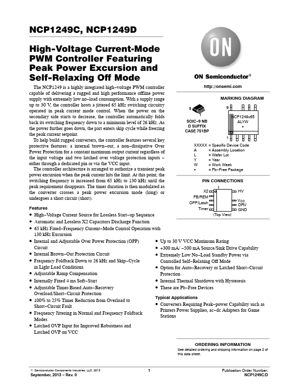
- High-Voltage Current Source for Lossless Start-up Sequence X2 FB/REM OPP/Latch Timer 1 (Top View) HV VCC DRV GND
- Automatic and Lossless X2 Capacitors Discharge Function
- 65 kHz Fixed-Frequency Current-Mode Control Operation with 130 kHz Excursion
- Internal and Adjustable Over Power Protection (OPP)
- Up to 30 V VCC Maximum Rating Circuit
- Internal Brown-Out Protection Circuit
- +300 mA/ -500 mA Source/Sink Drive Capability
- Extremely Low No-Load Standby Power via
- Frequency Foldback Down to 26 kHz and Skip-Cycle Controlled Self-Relaxing Off Mode in Light Load Conditions
- Adjustable Ramp pensation