pc2402f Overview
Key Features
- other Specs not available on catalog is under request
- w w w .D a S a t e e h U 4 t m o .c
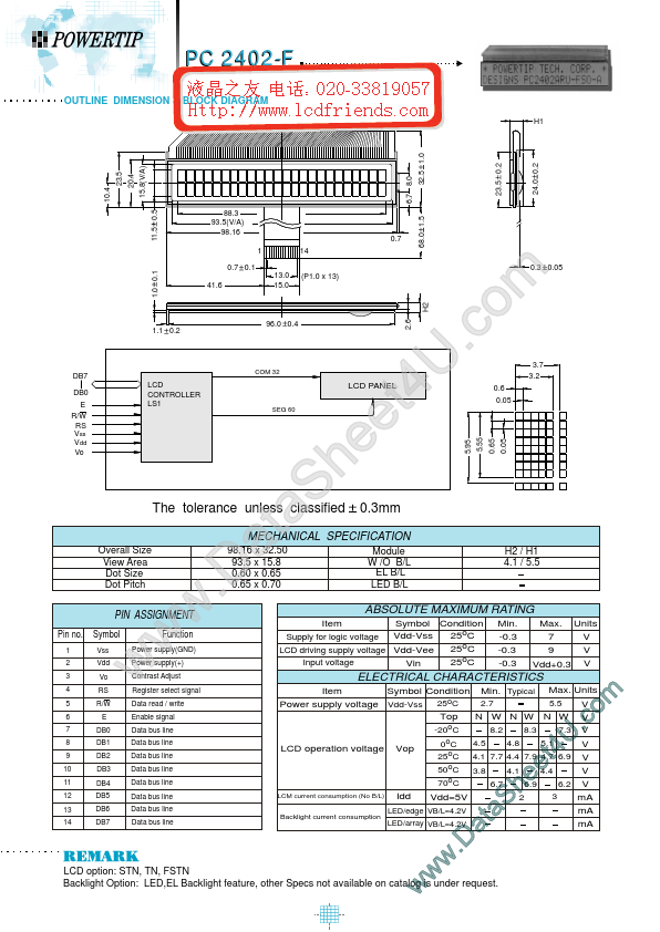
| Part | pc2402f |
|---|---|
| Description | LCD_Module |
| Manufacturer | POWERTIP |
| Size | 119.17 KB |
| Part Number | Manufacturer | Description |
|---|---|---|
| PC2402A-O | P-tec Corporation | Character Display |