pc2402l Overview
Key Specifications
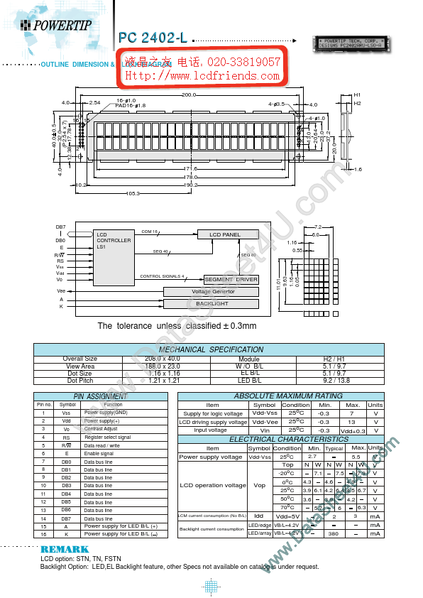
Package: Module
Height: 118 mm
Max Operating Temp: 50 °C
Min Operating Temp: 0 °C
Key Features
- other Specs not available on catalog is under request
- w w w .D a S a t e e h 4.9 U 4 t m o .c
| Part | pc2402l |
|---|---|
| Description | LCD_Module |
| Manufacturer | POWERTIP |
| Size | 118.11 KB |
Package: Module
Height: 118 mm
Max Operating Temp: 50 °C
Min Operating Temp: 0 °C
| Seller | Inventory | Price Breaks | Buy |
|---|---|---|---|
| element14 APAC | 0 | 1+ : 19.11 SGD 5+ : 17.29 SGD 10+ : 15.33 SGD 50+ : 14.39 SGD |
View Offer |
| Farnell | 0 | 1+ : 7.38 GBP | View Offer |
| Part Number | Manufacturer | Description |
|---|---|---|
| PC2402A-O | P-tec Corporation | Character Display |