A719
Overview
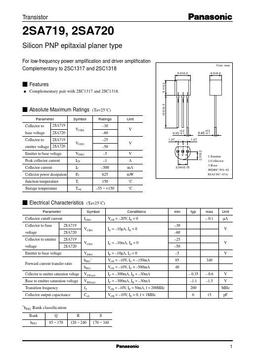
- 1±0.2
- 0±0.2 Unit: mm 4.0±0.2
- 5±0.5 s Absolute Maximum Ratings (Ta=25˚C) Parameter Symbol Ratings Unit Collector to 2SA719 -30 base voltage 2SA720 VCBO -60 V Collector to 2SA719 -25 VCEO V emitter voltage 2SA720 -50 Emitter to base voltage VEBO -5 V Peak collector current ICP -1 A Collector current IC -500 mA Collector power dissipation PC 625 mW Junction temperature Tj 150 ˚C Storage temperature Tstg -55 ~ +150 ˚C +0.2
- 45 -0.1 1.27 +0.2
- 45 -0.1 1.27
- 3±0.2 123 2.54±0.15 1:Emitter 2:Collector 3:Base JEDEC:TO-92 EIAJ:SC-43A s Electrical Characteristics (Ta=25˚C) Parameter Collector cutoff current Collector to base 2SA719 voltage 2SA720 Collector to emitter 2SA719 voltage 2SA720 Emitter to base voltage Forward current transfer ratio Collector to emitter saturation voltage Base to emitter saturation voltage Transition frequency Collector output capacitance Symbol ICBO VCBO VCEO VEBO hFE1* hFE2 VCE(sat) VBE(sat) fT Cob Conditions VCB = -20V, IE = 0 IC = -10µA, IE = 0 IC = -10mA, IB = 0 IE = -10µA, IC = 0 VCE = -10V, IC = -150mA VCE = -10V, IC = -500mA IC = -300mA, IB = -30mA IC = -300mA, IB = -30mA VCB = -10V, IE = 50mA, f = 200MHz VCB = -10V, IE = 0, f = 1MHz min typ max Unit - 0.1 µA -30 V -60 -25 V -50 -5 V 85 340 40 - 0.35 - 0.6 V -1.1 -1.5 V 200 MHz 6 15 pF
- hFE1 Rank classification Rank Q R hFE1 85 ~ 170 120 ~ 240 S 170 ~ 340 1 Collector power dissipation PC (mW) Transistor PC - Ta