MN86157
Overview
The MN86157 contains a 7-bit A/D converter for use in correcting, at the bit level, shading distortion for signals from image sensors, optics, and similar sources. It uses external RAM to support adaptive correction that responds to changes in distortion patterns. It also uses ROM to provide fixed correction when a white reference plane signal is not available. The chip is also usable as a stand-alone A/D converter.
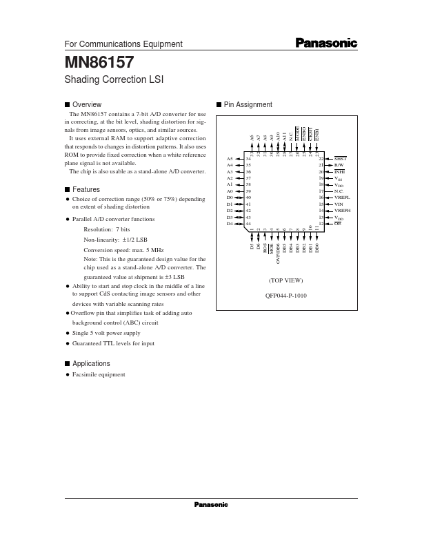
Pin Assignment
Features
Choice of correction range (50% or 75%) depending on extent of shading distortion Parallel A/D converter functions Resolution: 7 bits Non-linearity: ± 1/2 LSB Conversion speed: max. 5 MHz Note: This is the guaranteed design value for the chip used as a stand-alone A/D converter. The guaranteed value at shipment is ±3 LSB Ability to start and stop clock in the middle of a line to support Cd S contacting image sensors and other devices with variable scanning rates Overflow pin that simplifies task of adding auto background control (ABC)...