MJ1410 Overview
Key Features
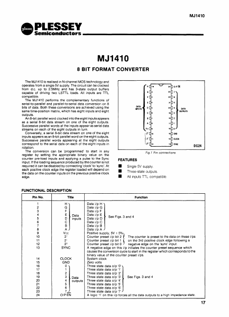
- Single 5V supply
- Three-state outputs
- All inputs TTL compatible. DG24
| Part | MJ1410 |
|---|---|
| Description | 8-BIT FORMAT CONVERTER |
| Manufacturer | Plessey |
| Size | 142.45 KB |
| Part Number | Manufacturer | Description |
|---|---|---|
| B2405S-2W | MORNSUN | DUAL/SINGLE OUTPUT DC-DC CONVERTER |
| CN3903 | Chipnet | 36V/3.5A 500KHz Synchronous Step-Down Converter |
| MC34063 | STMicroelectronics | DC-DC CONVERTER CONTROLLER |