MJ1445 Overview
Key Features
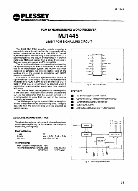
- 5V ± 5% Supply
- 20 mA Typical
- Conforms to CCITI Recommendation G732
- Synchronising Word Error Monitor
- Out of Sync. Alarm
- All Inputs and Outputs are TIL Compatible
| Part | MJ1445 |
|---|---|
| Description | 2-MBIT PCM SIGNALLING |
| Manufacturer | Plessey |
| Size | 112.79 KB |
| Part Number | Manufacturer | Description |
|---|---|---|
| FX-207 | CML | SELECTIVE SIGNALLING |
| MK5027 | STMicroelectronics | SS7 SIGNALLING LINK CONTROLLER |
| CMX138A | Consumer Microcircuits Limited | Audio Scrambler and Sub-Audio Signalling Processor |