QIS4506001
QIS4506001 is Single Discrete IGBT manufactured by Powerex, Inc.
..
Powerex, Inc., 173 Pavilion Lane, Youngwood 15697 (724) 925-7272 .pwrx. Single Discrete IGBT 60 Amperes /4500 Volts
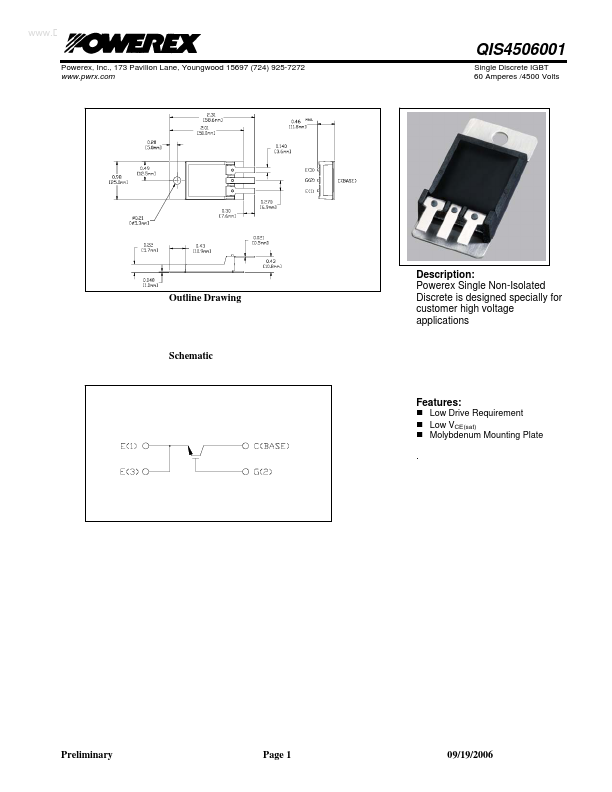
Outline Drawing
Description: Powerex Single Non-Isolated Discrete is designed specially for customer high voltage applications
Schematic
Features
:
- Low Drive Requirement
- Low VCE(sat)
- Molybdenum Mounting Plate .
Preliminary
Page 1
09/19/2006
Powerex, Inc., 173 Pavilion Lane, Youngwood 15697 (724) 925-7272 .pwrx. Single Discrete IGBT 60 Amperes /4500 Volts
Maximum Ratings, Tj=25°C unless otherwise specified
Ratings Collector Emitter Voltage Gate Emitter Voltage Collector Current (Continuous) Peak Collector Current (Pulsed) Junction Temperature Storage Temperature Mounting Torque, M5 Mounting Screws Weight (Typical) Symbol VCES VGES IC ICM Tj Tstg QIS4506001 4500 ±20 60 120- -55 to 150 -55 to 125 30 21 Units Volts Volts Amperes Amperes °C °C In-lb Grams
- Pulse width and repetition rate should be such that device junction temperature does not exceed device rating.
Static Electrical Characteristics, Tj=25°C unless otherwise specified
Characteristic Collector Cutoff Current Gate Leakage Current Gate-Emitter Threshold Voltage Collector-Emitter Saturation Voltage Symbol ICES IGES VGE(th) VCE(sat) Test Conditions VCE=VCES VGE=0V VGE=VGES VCE=0V IC=7m A, VCE=10V IC=67A, VGE=15V IC=67A, VGE=15V, Tj=125°C Total Gate Charge QG VCC=2250V, IC=67A, VGS=15V Min. 4.5 Typ. 6.0 3.0 3.6 800 Max. 1.0 0.5 7.5 3.9- Units m A µA Volts Volts Volts n C
- Pulse width and repetition rate should be such that device junction temperature rise is negligible.
Dynamic Electrical Characteristics, Tj=25°C unless otherwise specified
Characteristic Input Capacitance Output Capacitance Reverse Transfer Capacitance Turn on Delay time Rise Time Turn- off Delay Time Fall Time Symbol Cies Coes Cres td(on) tr td(off) tf Test Conditions VGE=0V VCE=10V f=1MHz VCC=2250V IC=67A VGE1=VGE2=15V RG=120Ω Min. Typ. 10 .7 .2 2.4 2.4 6.0...