X9111
X9111 is Single Digitally Potentiometer manufactured by Renesas.
Features
- 1024 resistor taps
- 10-bit resolution
- SPI serial interface for write, read, and transfer operations of the potentiometer
- Wiper resistance, 40Ω typical at 5V
- Four nonvolatile Data Registers
- Nonvolatile storage of multiple wiper positions
- Power-on recall, loads saved wiper position on power-up
- Standby current <3µA maximum
- VCC: 2.7V to 5.5V operation
- 100kΩ end-to-end resistance
- 100-year data retention
- Endurance: 100,000 data changes per bit per register
- 14 Ld TSSOP
- Low-power CMOS
- Single supply version of the X9110
- Pb-Free (Ro HS pliant)
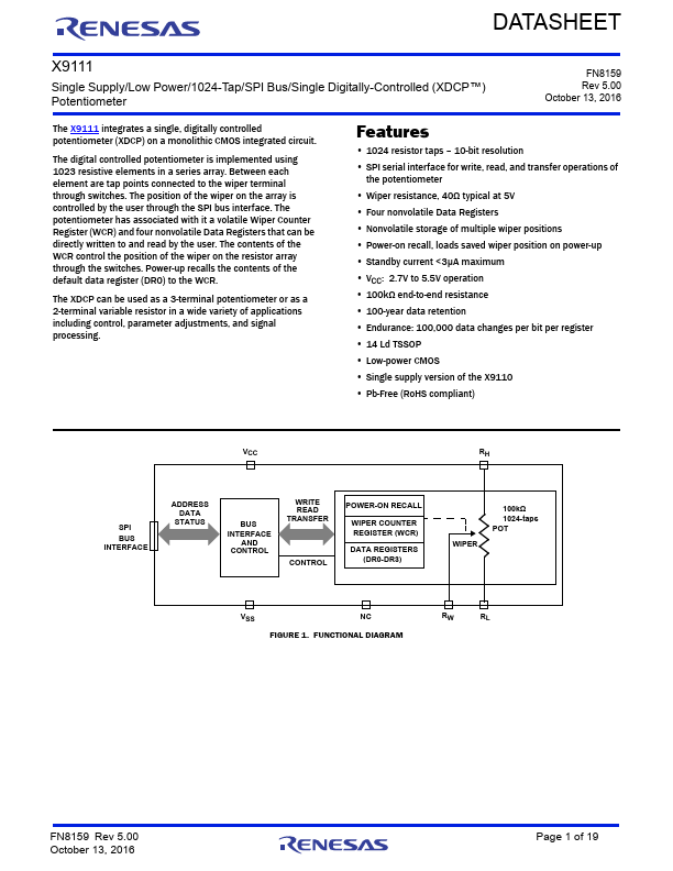
BUS INTERFACE
ADDRESS DATA
STATUS
INTERFACE AND
CONTROL
WRITE READ TRANSFER
CONTROL
POWER-ON RECALL
WIPER COUNTER REGISTER (WCR)
DATA REGISTERS (DR0-DR3)
WIPER
100kΩ 1024-taps POT
FIGURE 1. FUNCTIONAL DIAGRAM
RW RL
FN8159 Rev 5.00 October 13, 2016
Page 1 of 19
Circuit Level...