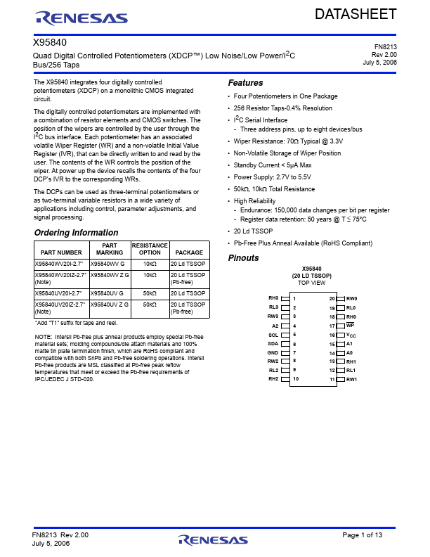
Datasheet4U Logo Datasheet4U.com

X95840 - Quad Digital Potentiometers

Description

TSSOP PIN SYMBOL 1 RH3 2 RL3 3 RW3 4 A2 5 SCL 6 SDA 7 GND 8 RW2 9 RL2 10 RH2 11 RW1 12 RL1 13 RH1 14 A0 15 A1 16 VCC 17 WP 18 RH0 19 RL0 20 RW0 WP GND DESCRIPTION “High” terminal of DCP3 “Low” terminal of DCP3 “Wiper” terminal of DCP3 Device address for the I2C interface I2C i

Features

  • Four Potentiometers in One Package.
  • 256 Resistor Taps-0.4% Resolution.
  • I2C Serial Interface - Three address pins, up to eight devices/bus.
  • Wiper Resistance: 70 Typical @ 3.3V.
  • Non-Volatile Storage of Wiper Position.
  • Standby Current < 5µA Max.
  • Power Supply: 2.7V to 5.5V.
  • 50k, 10k Total Resistance.
  • High Reliability - Endurance: 150,000 data changes per bit per register - Register data retention: 50 years @ T  75°.

📥 Download Datasheet

Datasheet preview – X95840

Datasheet Details

Part number X95840
Manufacturer Renesas
File Size 1.35 MB
Description Quad Digital Potentiometers
Datasheet download datasheet X95840 Datasheet
Additional preview pages of the X95840 datasheet.
Other Datasheets by Renesas

Full PDF Text Transcription

Click to expand full text
DATASHEET X95840 Quad Digital Controlled Potentiometers (XDCP™) Low Noise/Low Power/I2C Bus/256 Taps FN8213 Rev 2.00 July 5, 2006 The X95840 integrates four digitally controlled potentiometers (XDCP) on a monolithic CMOS integrated circuit. The digitally controlled potentiometers are implemented with a combination of resistor elements and CMOS switches. The position of the wipers are controlled by the user through the I2C bus interface. Each potentiometer has an associated volatile Wiper Register (WR) and a non-volatile Initial Value Register (IVR), that can be directly written to and read by the user. The contents of the WR controls the position of the wiper. At power up the device recalls the contents of the four DCP’s IVR to the corresponding WRs.
Published: |