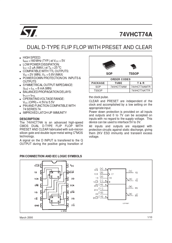
DESCRIPTION
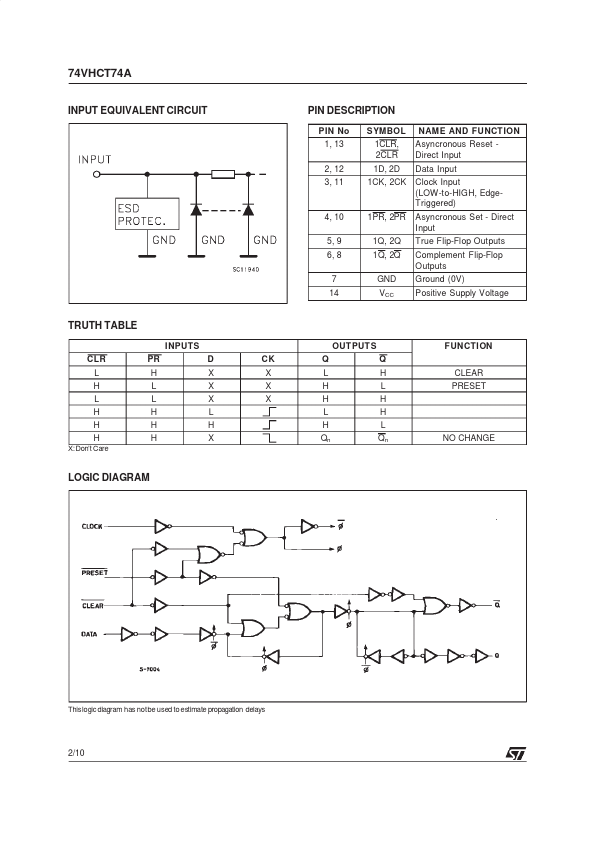
A signal on the D INPUT is transfered to the Q OUTPUT during the positive going transition of the clock pulse. CLEAR and PRESET are independent of the clock and accomplished by a low setting on the appropriate input. Power down protection is provided on all inputs and outputs and 0 to 7V can be accepted on inputs with no regard to the supply voltage. This device can be used to interface 5V to 3V. All inputs and outputs are equipped with protection circuits against static discharge, giving them 2KV ESD immunity and transient excess voltage. PIN CONNECTION AND IEC LOGIC SYMBOLS March 2000 1/10 74VHCT74A INPUT EQUIVALENT CIRCUIT PIN DESCRIPTION
PIN No 1, 13 2, 12 3, 11 SYMBOL 1CLR, 2CLR 1D, 2D 1CK, 2CK NAME AND FUNCT ION Asyncronous Reset Direct Input Data Input Clock Input (LOW-to-HIGH, EdgeTriggered) Asyncronous Set - Direct Input True Flip-Flop Outputs Complement Flip-Flop Outputs Ground (0V) Positive Supply Voltage 4, 10 5, 9 6, 8 7 14 1PR, 2PR 1Q, 2Q 1Q, 2Q GND VCC TRUTH... STMicroelectronics