DESCRIPTION
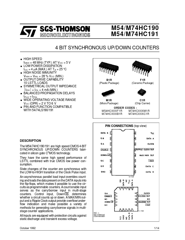
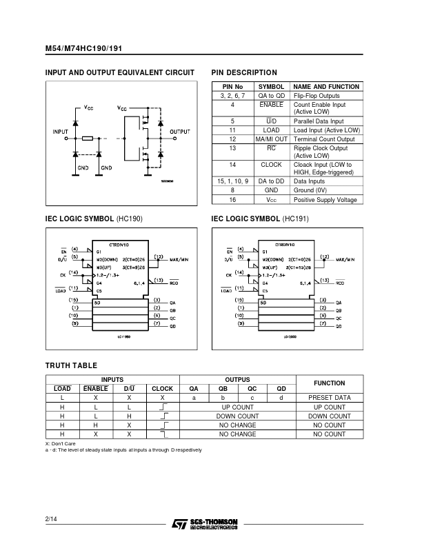
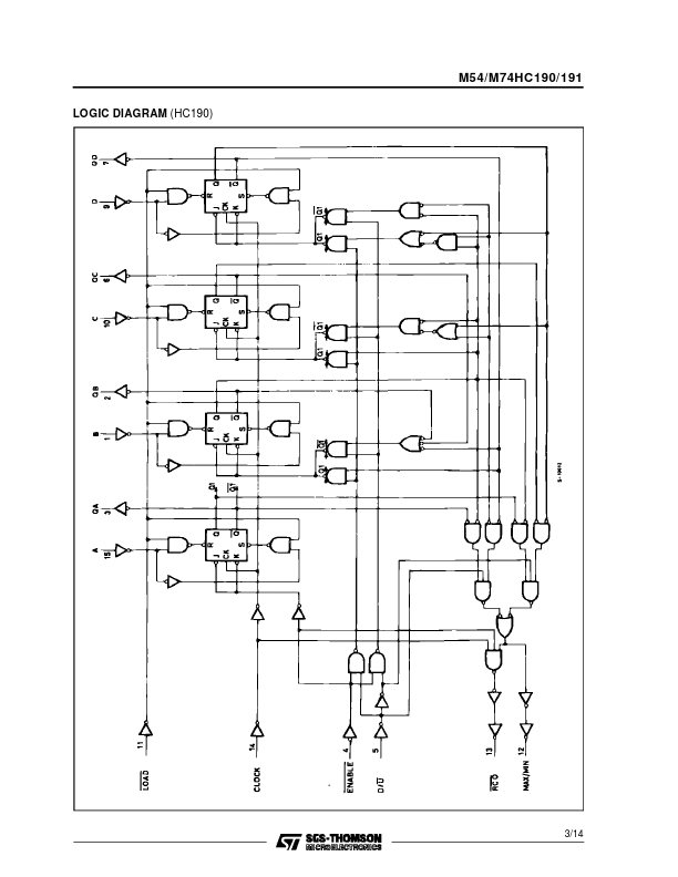
State changes of the counter are synchronous with the LOW-to-HIGH transition of the Clock Pulse input. An asynchronous parallel load input overrides counting and loads the data present on the DATA inputs into the flip-flops, which makes it possible to use the circuits as programmable counters. A countenable input serves as the carry/borrow input in multi-stage counters. Control input, Down/Up, determines whether a circuit counts up or down. A MAX/MIN output and a Ripple Clock output provide overflow/underflow indication and make possible a variety of methods for generating carry/borrow signals in multistage counter applications. All inputs are equipped with protection circuits against static discharge and transient excess voltage. NC = No Internal Connection October 1992 1/14 M54/M74HC190/191 INPUT AND OUTPUT EQUIVALENT CIRCUIT IEC LOGIC SYMBOL (HC190) PIN DESCRIPTION
PIN No 3, 2, 6, 7 4 5 11 12 13 14 15, 1, 10, 9 8 16 SYMBOL NAME AND FUNCTION QA to QD Flip-Flop Outputs ENA... STMicroelectronics