DESCRIPTION
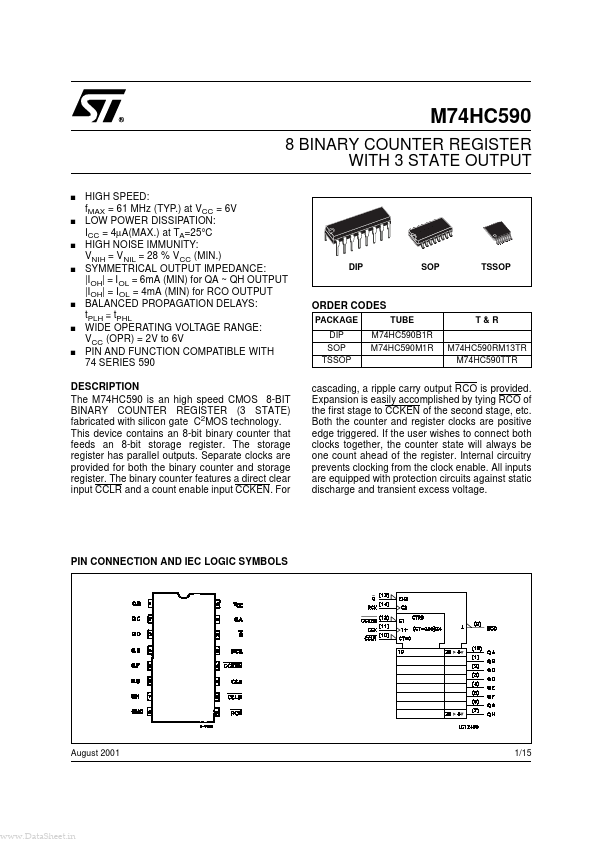
The storage register has parallel outputs. Separate clocks are provided for both the binary counter and storage register. The binary counter features a direct clear input CCLR and a count enable input CCKEN. For cascading, a ripple carry output RCO is provided. Expansion is easily accomplished by tying RCO of the first stage to CCKEN of the second stage, etc. Both the counter and register clocks are positive edge triggered. If the user wishes to connect both clocks together, the counter state will always be one count ahead of the register. Internal circuitry prevents clocking from the clock enable. All inputs are equipped with protection circuits against static discharge and transient excess voltage. PIN CONNECTION AND IEC LOGIC SYMBOLS August 2001 1/15 M74HC590 INPUT AND OUTPUT EQUIVALENT CIRCUIT PIN DESCRIPTION
PIN No 1, 2, 3, 4, 5, 6, 7, 15 11 12 13 9 14 10 8 16 SYMBOL QA to QH CCK CCKEN RCK RCO G CCLR GND VCC NAME AND FUNCTION Outputs Counter Clock Input Counter Clock E... STMicroelectronics