STMicroelectronics TSM114
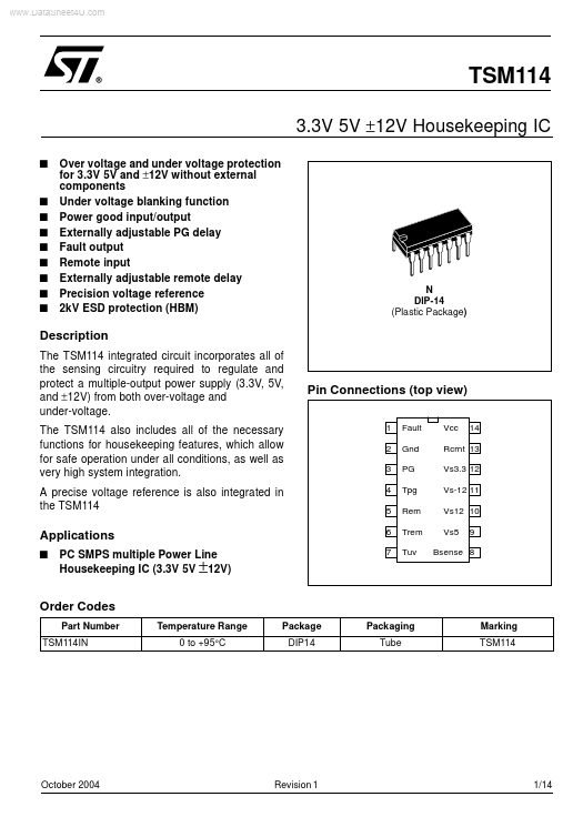
The TSM114 integrated circuit incorporates all of the sensing circuitry required to regulate and protect a multiple-output power supply (3.3V, 5V, and ±12V) from both over-voltage and under-voltage. The TSM114 also includes all of the necessary functions for housekeeping features, which allow for safe operation under all conditions, as well as very high system integration. This pin goes low upon an under voltage condition.| Part No. | TSM114 |
|---|---|
| Datasheet | TSM114 Download |
| Manufacturer |  STMicroelectronics |
| Description | Housekeeping IC |
| Buy | Stock & Price |
DESCRIPTION
A precise voltage reference is also integrated in the TSM114 Pin Connections (top view) 1 2 3 4 5 6 7 Fault Gnd PG Tpg Rem Trem Tuv Vcc 14 Rcrnt 13 Vs3.3 12 Vs-12 11 Vs12 10 Vs5 9APPLICATIONS
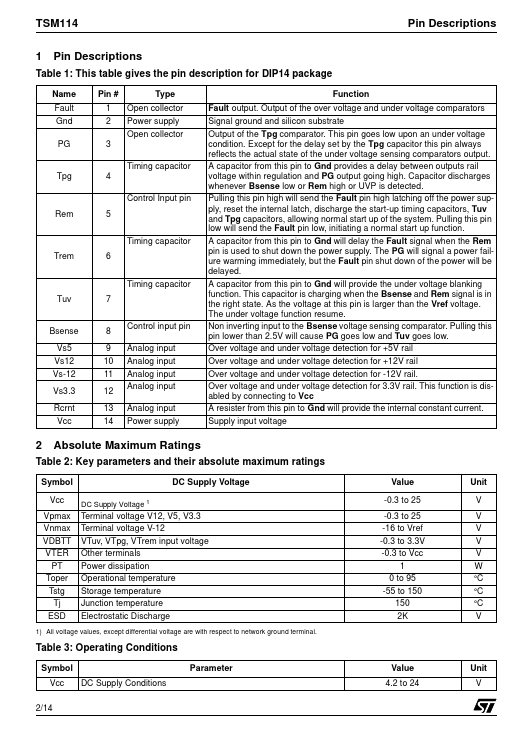
s PC SMPS multiple Power Line Housekeeping IC (3.3V 5V ±12V) Bsense 8 Order Codes Part Number TSM114IN Temperature Range 0 to +95°C Package DIP14 Packaging Tube Marking TSM114 October 2004 Revision 1 1/14 TSM114 1 Pin Descriptions Pin Descriptions Table 1: This table gives the pin description for DIP14 package Name Fault Gnd PG Pin # 1 2 3 Timing capacitor Tpg 4 Control Input pin Rem 5 Timing capacitor Trem 6 Timing capacitor Tuv 7 Control input pin Analog input Analog input Analog input Analog input Analog input Power supply Type Open collector Power supply Open collector Function Fault output. Output of the over voltage and under voltage comparators Signal ground and silicon substrate Output of the Tpg comparator. Except for the delay set by the Tpg capacitor this pin always reflects the actual state of the under voltage sensing comparators output.