• Part: SPC5604
  • Description: N & P Pair Enhancement Mode MOSFET
  • Category: MOSFET
  • Manufacturer: SYNC POWER
  • Size: 513.11 KB
Download SPC5604 Datasheet PDF
SYNC POWER
SPC5604
SPC5604 is N & P Pair Enhancement Mode MOSFET manufactured by SYNC POWER.
DESCRIPTION 
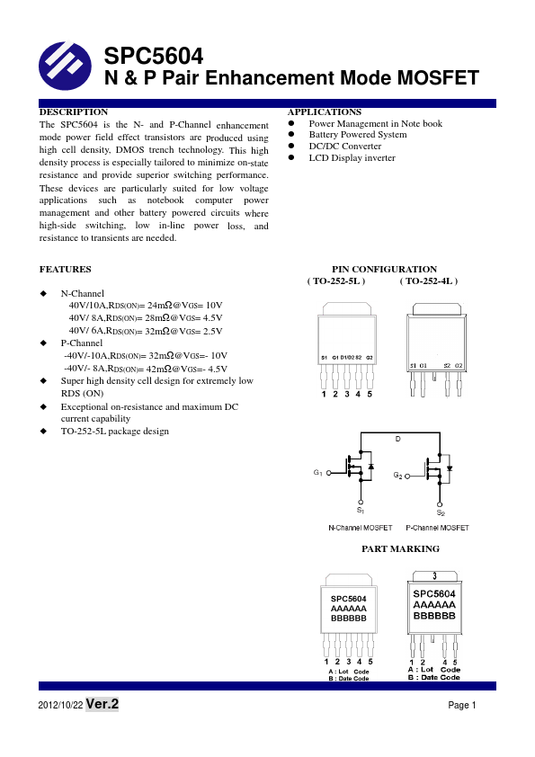
The SPC5604 is the N- and P-Channel enhancement mode power field effect transistors are produced using high cell density, DMOS trench technology. This high density process is especially tailored to minimize on-state resistance and provide superior switching performance. These devices are particularly suited for low voltage applications such as notebook puter power management and other battery powered circuits where high-side switching, low in-line power loss, and resistance to transients are needed. FEATURES N-Channel 40V/10A,RDS(ON)= 24mΩ@VGS= 10V 40V/ 8A,RDS(ON)= 28mΩ@VGS= 4.5V 40V/ 6A,RDS(ON)= 32mΩ@VGS= 2.5V P-Channel -40V/-10A,RDS(ON)= 32mΩ@VGS=- 10V -40V/- 8A,RDS(ON)= 42mΩ@VGS=- 4.5V Super high density cell design for extremely low RDS (ON) Exceptional on-resistance and maximum DC current capability TO-252-5L package design APPLICATIONS Power Management in Note book Battery Powered System DC/DC Converter LCD Display inverter PIN CONFIGURATION ( TO-252-5L ) ( TO-252-4L ) PART MARKING 2012/10/22 Ver.2 Page 1 http://.. N & P Pair Enhancement Mode MOSFET PIN DESCRIPTION Pin 1 2 3 4 5 Description (TO-252-5L) Source 1 Gate 1 Drain1/Drain2 Source 2 Gate 2 Description (TO-252-4L) Source 1 Gate 1 Drain Source 2 Gate 2 ORDERING INFORMATION Part Number SPC5604T255RGB SPC5604T254RGB Package T0-252-5L T0-252-4L Part Marking SPC5604 SPC5604 ※ SPC5604T255RGB: 13” Tape Reel ; Pb - Free ; Halogen - Free ※ SPC5604T254RGB :13” Tape Reel ; Pb - Free ; Halogen - Free ABSOULTE MAXIMUM RATINGS (TA=25℃ Unless otherwise noted) Typical Parameter Drain-Source Voltage Gate - Source Voltage Continuous Drain Current(TJ=150℃) Pulsed Drain Current Continuous Source Current(Diode Conduction) Power Dissipation Operating Junction Temperature Storage Temperature Range Thermal Resistance-Junction to Ambient T ≤ 10sec Steady State TA=25℃ TA=70℃ TA=25℃ TA=70℃ Symbol N-Channel VDSS VGSS ID IDM IS PD TJ TSTG RθJA P-Channel Unit 40 ±20 10.0 7.0 25 2.3 2.5 1.6 -55/150...