Datasheet4U Logo Datasheet4U.com

HRLF80N06K - N-Channel MOSFET

Features

  • ‰ BVDSS = 60 V ‰ ID = 70 A ‰ Unrivalled Gate Charge : 100 nC (Typ. ) ‰ Lower RDS(ON) : 6.3 Pȍ (Typ. ) @VGS=10V ‰ Lower RDS(ON) : 7.5 Pȍ (Typ. ) @VGS=4.5V ‰ 100% Avalanche Tested 8DFN 5x6 1 Absolute Maximum Ratings TJ=25୅ unless otherwise specified Symbol Parameter Value VDSS VGS ID IDM EAS PD TJ, TSTG Drain-Source Voltage Gate-Source Voltage Drain Current Pulsed Drain Current TC = 25୅ TC = 100୅ (Note 1) Single Pulsed Avalanche Energy (Note 2) Power Dissipation TC= 25୅ TA = 25୅ Operat.

📥 Download Datasheet

Datasheet preview – HRLF80N06K

Datasheet Details

Part number HRLF80N06K
Manufacturer SemiHow
File Size 184.74 KB
Description N-Channel MOSFET
Datasheet download datasheet HRLF80N06K Datasheet
Additional preview pages of the HRLF80N06K datasheet.
Other Datasheets by SemiHow

Full PDF Text Transcription

Click to expand full text
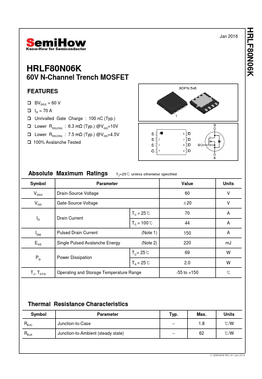
HRLF80N06K Jan 2016 HRLF80N06K 60V N-Channel Trench MOSFET FEATURES ‰ BVDSS = 60 V ‰ ID = 70 A ‰ Unrivalled Gate Charge : 100 nC (Typ.) ‰ Lower RDS(ON) : 6.3 Pȍ (Typ.) @VGS=10V ‰ Lower RDS(ON) : 7.5 Pȍ (Typ.) @VGS=4.5V ‰ 100% Avalanche Tested 8DFN 5x6 1 Absolute Maximum Ratings TJ=25୅ unless otherwise specified Symbol Parameter Value VDSS VGS ID IDM EAS PD TJ, TSTG Drain-Source Voltage Gate-Source Voltage Drain Current Pulsed Drain Current TC = 25୅ TC = 100୅ (Note 1) Single Pulsed Avalanche Energy (Note 2) Power Dissipation TC= 25୅ TA = 25୅ Operating and Storage Temperature Range 60 ρ20 70 44 150 220 69 2.0 -55 to +150 Units V V A A A mJ W W ୅ Thermal Resistance Characteristics Symbol Parameter RșJC RșJA Junction-to-Case Junction-to-Ambient (steady state) Typ.
Published: |