BFP490
BFP490 is NPN Silicon RF Transistor manufactured by Siemens Semiconductor Group.
SIEGET® 25
NPN Silicon RF Transistor Preliminary data
- For high power amplifiers
- pression point P-1d B = 26.5 d Bm at 1.8 GHz maxim. available Gain Gma = 9.5 d B at 1.8 GHz
- Transition frequency f T > 17 GHz
- Gold metalization for high reliability
- SIEGET ® 25
- Line Siemens Grounded Emitter Transistor 25 GHz f T
- Line
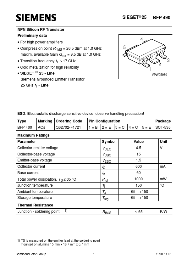
BFP 490
4 5 3 2 1
VPW05980
ESD: Electrostatic discharge sensitive device, observe handling precaution! Type BFP 490 Marking Ordering Code AOs Q62702-F1721 Pin Configuration 1=B 2=E 3=C 4=C 5=E Package SCT-595
Maximum Ratings Parameter Collector-emitter voltage Collector-base voltage Emitter-base voltage Collector current Base current Total power dissipation, T S ≤ 85 °C Junction temperature Ambient temperature Storage temperature Thermal Resistance Junction
- soldering point
1)
Symbol
Value 4.5 15 1.5 600 60 1000 150 -65 ...+150 -65 ...+150
Unit V
VCEO VCBO VEBO IC IB Ptot Tj TA Tstg Rth JS m A m W °C
≤ 65
K/W
1) TS is measured on the emitter lead at the soldering point mounted on alumina 15 mm x 16,7 mm x 0.7 mm Semiconductor Group Semiconductor Group 11
Sep-09-1998 1998-11-01
BFP 490
Electrical Characteristics at TA = 25°C, unless otherwise specified. Parameter Symbol Values min. DC characteristics Collector-emitter breakdown voltage I C = 1 m A, I B = 0 Collector-base cutoff current VCB = 5 V, IE = 0 Emitter-base cutoff current VEB = 1.5 V, I C = 0 DC current gain I C = 200 m A, V CE = 3 V
AC characteristics Transition frequency IC = 300 m A, VCE = 3 V, f = 0.2 GHz IC = 300 m A, VCE = 3 V, f = 0.5 GHz Collector-base capacitance VCB = 2 V, f = 1 MHz Collector-emitter capacitance VCE = 2 V, f = 1 MHz Emitter-base capacitance VEB = 0.5 V, f = 1 MHz Noise figure IC = 100 m A, VCE = 2 V, ZS = ZSopt , f = 1.8 GHz Power gain 2) IC = 200 m A, VCE = 2 V, ZS = ZSopt, ZL = ZLopt , f = 1.8 GHz Insertion power gain IC = 200 m A, VCE = 2 V, f = 0.5 GHz, ZS = ZL = 50Ω Third order intersept point IC = 300 m A, VCE = 3 V, ZS=ZSopt , ZL=ZLopt , f = 1.8 GHz...