HYS72V2100GCU-10
3.3V 2M x 64-Bit SDRAM Module 3.3V 2M x 72-Bit SDRAM Module 168 pin unbuffered DIMM Modules
HYS64V2100G(C)U-10 HYS72V2100G(C)U-10
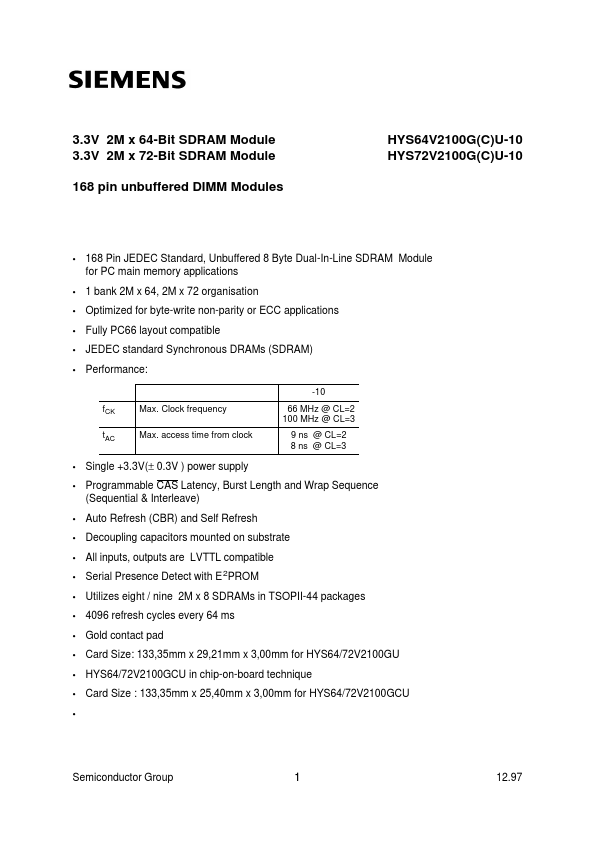
- 168 Pin JEDEC Standard, Unbuffered 8 Byte Dual-In-Line SDRAM Module for PC main memory applications 1 bank 2M x 64, 2M x 72 organisation Optimized for byte-write non-parity or ECC applications Fully PC66 layout patible JEDEC standard Synchronous DRAMs (SDRAM) Performance:
-10 f CK t AC Max. Clock frequency Max. access time from clock 66 MHz @ CL=2 100 MHz @ CL=3 9 ns @ CL=2 8 ns @ CL=3
- -
- -
- -
- Single +3.3V(± 0.3V ) power supply Programmable CAS Latency, Burst Length and Wrap Sequence (Sequential & Interleave) Auto Refresh (CBR) and Self Refresh Decoupling capacitors mounted on substrate All inputs, outputs are LVTTL patible Serial Presence Detect with E 2PROM Utilizes eight / nine 2M x 8 SDRAMs in TSOPII-44 packages 4096 refresh cycles every 64 ms Gold contact pad Card Size: 133,35mm x 29,21mm x 3,00mm for HYS64/72V2100GU HYS64/72V2100GCU in...