SKY65120
SKY65120 is WCDMA PA Bias Method manufactured by Skyworks Solutions.
Description
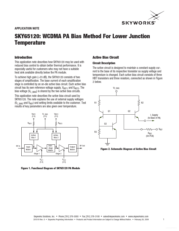
The active circuit is designed to maintain a constant supply current to the base of its respective transistor as supply voltage and temperature is changed. Each active bias circuit consists of three HBT transistors and three resistors, connected as shown in Figure 2 below.
VC_BIAS
R1 Q1 Q2
R2
I_Supply (to Base of PA) Q3 R3 VREF RREF (On PCB)
Active Bias 1
Active Bias 2
RF In
Input Match Stage 1 VCC1 (5 V)
Interstage Match Stage 2 VCC2 (5 V)
Output Match
RF Out
Figure 2. Schematic Diagram of Active Bias Circuit
Figure 1. Functional Diagram of SKY65120 PA Module
Skyworks Solutions, Inc.
- Phone [781] 376-3000
- Fax [781] 376-3100
- sales@skyworksinc.
- .skyworksinc. 201019 Rev. A
- Skyworks Proprietary Information
- Products and Product Information are Subject to Change Without Notice.
- February 26, 2009
Free Datasheet http://.n Datasheet.
Application Note
- SKY65120: WCMDA PA Bias Method For Lower Junction Temperature
Transistor Q3 is used as a thermal reference VT monitor, and is located on-die close to the amplifier transistor. This configuration allows stable PA module operation as the amplifier temperature changes. The main supply voltage to the bias circuits, Vc_Bias, should be set to 5 V, and is internally connected to both bias circuits. Reference voltages, Vref1 and Vref2 are made available to the user to allow PA ON/OFF switching; and a certain amount of gain and current control. When the Vref voltages are set to zero, Q1 and Q2 switches off, and effectively remove the supply current to the associated amplifier stage. Reference resistors, Rref1 and Rref2 (located on the customer PCB) can be used to trim the base reference current. Alternately, the Rref can be fixed and Vref voltages can be modified. For Vref1 = Vref2 = 5 V, the remended values for these reference resistors are: Rref1 = 390 Ohms, Rref2 = 120 Ohms.
J1 RF_IN 20 GND8 1 2 3 VC_BIAS C13 10 µF C1 3300 p F 4 5 6 19 GND7 18 NC5 17 GND6 16 15 14 13...