SMS7630-061
SMS7630-061 is 0201 Zero Bias Silicon Schottky Detector Diode manufactured by Skyworks Solutions.
Features
- Extremely low barrier height
- Suitable for use above 26 GHz
- Low parasitic impedance: CP < 0.05 p F, LS < 0.2 n H
- Low profile, ultra-miniature 0201 SMT package
(MSL1, 260 C per JEDEC J-STD-020)
Skyworks Green TM products are pliant with all applicable legislation and are halogen-free. For additional information, refer to Skyworks Definition of Green TM, document number SQ04- 0074.
Description
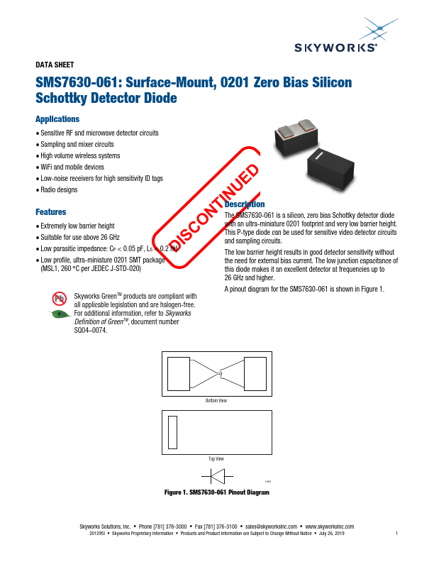
The SMS7630-061 is a silicon, zero bias Schottky detector diode with an ultra-miniature 0201 footprint and very low barrier height. This P-type diode can be used for sensitive video detector circuits and sampling circuits.
The low barrier height results in good detector sensitivity without the need for external bias current. The low junction capacitance of this diode makes it an excellent detector at frequencies up to 26 GHz and higher.
A pinout diagram for the SMS7630-061 is shown in Figure 1.
Bottom View
Top View
Y1952
Figure 1. SMS7630-061 Pinout Diagram
Skyworks Solutions, Inc.
- Phone [781] 376-3000
- Fax [781] 376-3100
- sales@skyworksinc.
- .skyworksinc.
201295I
- Skyworks Proprietary Information
- Products and Product Information are Subject to Change Without Notice
- July 26, 2019
DATA SHEET
- SMS7630-061: SURFACE-MOUNT, 0201 ZERO BIAS SILICON SCHOTTKY DETECTOR DIODE
Mixer and Detector Applications
24 GHz Detector Design
A detector circuit that incorporates an SMS7630-061 Schottky diode and covers the 24 GHz band is shown in Figure 2. The RF arrives on a 50 Ω microstrip line from the left and is shorted to GND by a 90 degree line with a stud (GND arrives by a via).
The cathode of the diode is directly connected to a 24 GHz stub. This output is loaded by a 100 kΩ resistor and a 100 p F capacitor. The output voltage is fed to a 2-pin, 2.54 mm header.
The circuit was built on a 0.254 mm Rogers RO-4350B substrate and measured with a power-variable 24 GHz source. A layout design is illustrated in Figure 3.
Input power versus detected voltage for this...