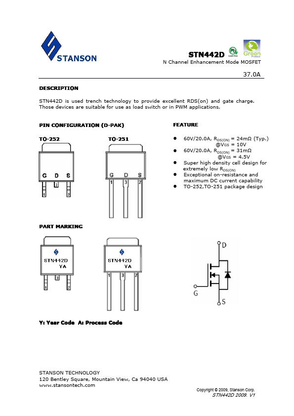
DESCRIPTION
Those devices are suitable for use as load switch or in PWM applications. PIN CONFIGURATION (D-PAK) TO-252 TO-251 FEATURE 60V/20.0A, RDS(ON) = 24mΩ (Typ.) @VGS = 10V 60V/20.0A, RDS(ON) = 31mΩ @VGS = 4.5V Super high density cell design for extremely low RDS(ON) Exceptional on-resistance and maximum DC current capability TO-252,TO-251 package design PART MARKING Y: Year Code A: Process Code STANSON TECHNOLOGY 120 Bentley Square, Mountain View, Ca 94040 USA Copyright © 2009, Stanson Corp. STN442D 2009. V1 STN442D N Channel Enhancement Mode MOSFET 37.0A ABSOULTE MAXIMUM RATINGS
(Ta = 25℃ Unless otherwise noted ) Parameter Symbol Drain-Source Voltage VDSS Gate-Source Voltage Continuous Drain Current (TJ=150℃) TA=25℃ TA=70℃ Pulsed Drain Current VGSS ID IDM Continuous Source Current (Diode Conduction) Power Dissipation TA=25℃ TA=70℃ Operation Junction Temperature IS PD TJ Storgae Temperature Range TSTG Thermal Resistance-Junction to Ambient RθJA Typical 60 ±20 37.0 26.0 60 32 60 30 175 -55/175 62 Unit V V A A A W ℃ ℃ ℃/W STANSON TECHNOLOGY 120 Bentley Square, Mountain View, Ca 94040 USA Copyright © 2009, Stanson Corp. Stanson