CW01
CW01 is Continuous Wave Transmitter manufactured by Supertex.
.DataSheet.co.kr
Supertex inc.
Four-Channel, Low Phase Noise, Low Power, Continuous Wave Transmitter
Features
- - Low phase noise
- - 100V open drain N-channel
- - High speed D flip-flop
- - High speed MOSFET gate driver
- - Up to 200MHz clock input
- - VDD and VLL undervoltage lockout
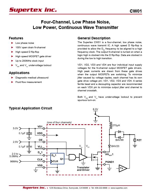
The Supertex CW01 is a four-channel, low phase noise, continuous wave transmit IC. A high speed D flip-flop is provided to allow the DIN frequency to be aligned to a high frequency clock. The output N-channel is turned on when a logic high is clocked into the D flip-flop. Data are clocked in during the low to high transition. VD1, VD2, VD3 and VD4 are four individual input supply voltages for the...