CP301 Overview
Key Specifications
Key Features
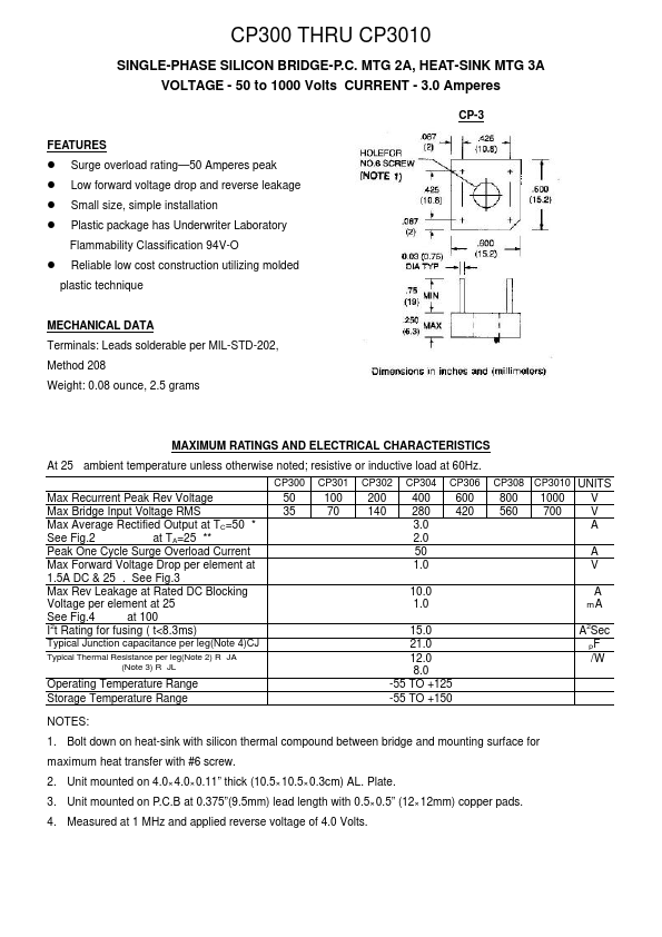
- 50 to 1000 Volts CURRENT
| Part | CP301 |
|---|---|
| Description | SINGLE-PHASE SILICON BRIDGE-P.C. MTG 2A/ HEAT-SINK MTG 3A |
| Manufacturer | TRSYS |
| Size | 123.84 KB |
| Seller | Inventory | Price Breaks | Buy |
|---|---|---|---|
| DigiKey | 5 | 1+ : 230.04 USD 10+ : 195.561 USD 25+ : 183.3336 USD 50+ : 181.0624 USD |
View Offer |
| TME | 0 | 1+ : 259.35 EUR 3+ : 214.34 EUR 5+ : 176.44 EUR |
View Offer |
| Part Number | Manufacturer | Description |
|---|---|---|
| CP301 | PanJit Semiconductor | SINGLE-PHASE SILICON BRIDGE-P.C. MTG 2A/ HEAT-SINK MTG 3A(VOLTAGE - 50 to 1000 Volts CURRENT - 3.0 Amperes) |
| CP3010 | PanJit Semiconductor | SINGLE-PHASE SILICON BRIDGE-P.C. MTG 2A/ HEAT-SINK MTG 3A(VOLTAGE - 50 to 1000 Volts CURRENT - 3.0 Amperes) |
| CP306 | PanJit Semiconductor | SINGLE-PHASE SILICON BRIDGE-P.C. MTG 2A/ HEAT-SINK MTG 3A(VOLTAGE - 50 to 1000 Volts CURRENT - 3.0 Amperes) |
| CP302 | PanJit Semiconductor | SINGLE-PHASE SILICON BRIDGE-P.C. MTG 2A/ HEAT-SINK MTG 3A(VOLTAGE - 50 to 1000 Volts CURRENT - 3.0 Amperes) |
| CP304 | PanJit Semiconductor | SINGLE-PHASE SILICON BRIDGE-P.C. MTG 2A/ HEAT-SINK MTG 3A(VOLTAGE - 50 to 1000 Volts CURRENT - 3.0 Amperes) |