DESCRIPTION
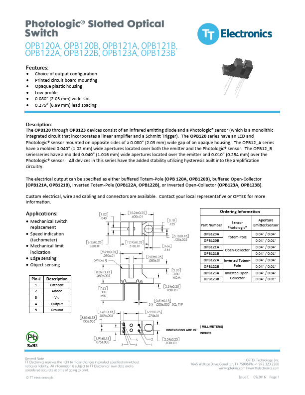
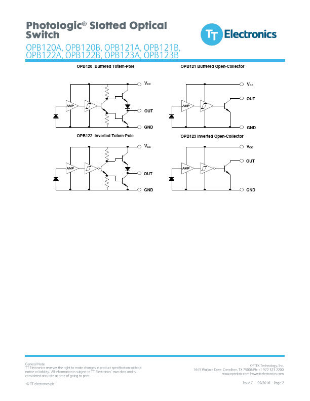
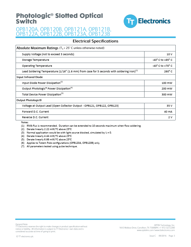
Cathode Anode VCC Output Ground Part Number Sensor Photologic® Aperture Emitter/Sensor OPB120A OPB120B Totem-Pole 0.04" / 0.04" 0.04" / 0.01" OPB121A 0.04" / 0.04" Open-Collector OPB121B 0.04" / 0.01" OPB122A Inverted Totem- 0.04" / 0.04" OPB122B Pole 0.04" / 0.01" OPB123A Inverted Open- 0.04" / 0.04" OPB123B Collector 0.04" / 0.01" RoHS [ MILLIMETERS] DIMENSIONS ARE IN: INCHES OPB120 Buffered Totem-Pole VCC OUT OPB122 Inverted Totem-Pole GND VCC OUT GND OPB121 Buffered Open-Collector VCC OUT GND OPB123 Inverted Open-Collector VCC OUT GND Supply Voltage (not to exceed 3 seconds) Storage Temperature Operating Temperature Lead Soldering Temperature (1/16” (1.6 mm) from case for 5 seconds with soldering iron)(1) Input Diode Power Dissipation(2) Output Photologic® Power Dissipation(4) Total Device Power Dissipation(5) Voltage at Output Lead (Open Collector Output - OPB121, OPB122, OPB123) Forward D.C. Current Reverse D.C. Current Notes: (1) RMA flux is recommended. Duration can... TT