TA8463F Description
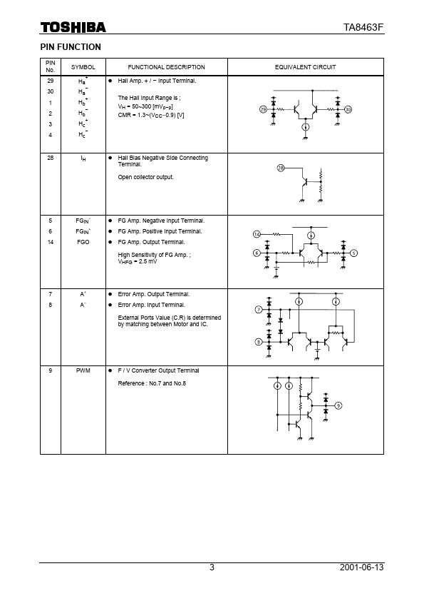
30 Ha− 1 Hb+ 2 Hb− 3 Hc+ The Hall Input Range is ; VH = 50~300 [mVp−p] CMR = 1.3~(VCC-0.9) [V] 4 Hc− 28 IH l Hall Bias Negative Side Connecting Terminal. High Sensitivity of FG Amp.
TA8463F Key Features
- Input Terminal
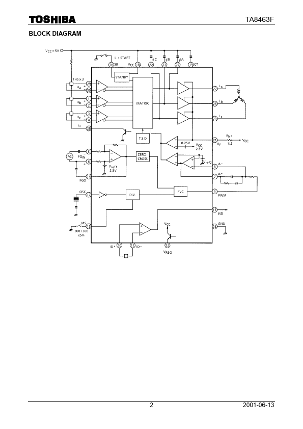
TA8463F is SINGLE CHIP 3 PHASE MOTOR DRIVER FOR FDD SPINDLE MOTOR manufactured by Toshiba.
| Part Number | Description |
|---|---|
| TA8461F | DUAL POWER OPERATIONAL AMPLIFIER |
| TA8462F | FAN MOTOR DRIVER IC |
| TA8462FG | FAN MOTOR DRIVER IC |
| TA8464K | DUAL POWER OPERATIONAL AMPLIFIER |
| TA8466AF | 3 PHASE FULL WAVE BRUSHLESS DC MOTOR DRIVER IC |
30 Ha− 1 Hb+ 2 Hb− 3 Hc+ The Hall Input Range is ; VH = 50~300 [mVp−p] CMR = 1.3~(VCC-0.9) [V] 4 Hc− 28 IH l Hall Bias Negative Side Connecting Terminal. High Sensitivity of FG Amp.