Datasheet Summary
8 Bit Microcontroller
TLCS-870/C1 Series
© 2009 TOSHIBA CORPORATION All Rights Reserved
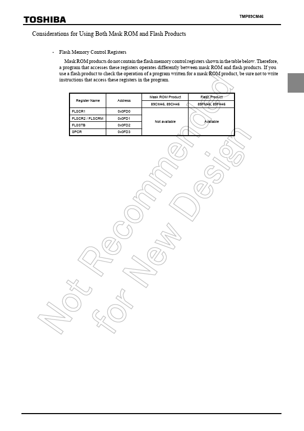
Considerations for Using Both Mask ROM and Flash Products
- Flash Memory Control Registers
Mask ROM products do not contain the flash memory control registers shown in the table below. Therefore, a program that accesses these registers operates differently between mask ROM and flash products. If you use a flash product to check the operation of a program written for a mask ROM product, be sure not to write instructions that access these registers in the program.
Register Name
FLSCR1 FLSCR2 / FLSCRM FLSSTB SPCR
Address
0x0FD0 0x0FD1 0x0FD2 0x0FD3
Mask ROM Product 89CM46,...