Vishay IRFBC40AS
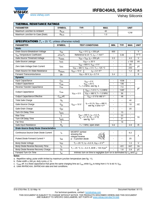
This document is subject to change without notice. THE PRODUCTS DESCRIBED HEREIN AND THIS DOCUMENT ARE SUBJECT TO SPECIFIC DISCLAIMERS, SET FORTH AT IRFBC40AS, SiHFBC40AS Vishay Siliconix THERMAL RESISTANCE RATINGS PARAMETER SYMBOL Maximum Junction-to-Ambient Maximum Junction-to-Case (Drain) RthJA RthJC TYP.| Part No. | IRFBC40AS |
|---|---|
| Datasheet | IRFBC40AS Download |
| Manufacturer |  Vishay |
| Description | Power MOSFET |
| Buy | Stock & Price |
FEATURES
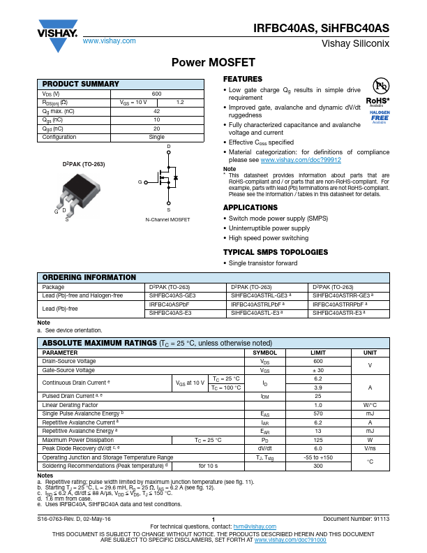
● Halogen-free According to IEC 61249-2-21 Definition● Low Gate Charge Qg results in Simple Drive Requirement
● Improved Gate, Avalanche and Dynamic dV/dt Ruggedness
● Fully Characterized Capacitance and Avalanche Voltage and Current
● Effective Coss Specified
● Compliant to RoHS Directive 2002/95/EC
APPLICATIONS
● Switch Mode Power Supply (SMPS)● Uninterruptible Power Supply
● High Speed Power Switching TYPICAL SMPS TOPOLOGIES
● Single Transistor Forward D2PAK (TO-263) SiHFBC40ASTRL-GE3a IRFBC40ASTRLPbFa SiHFBC40ASTL-E3a D2PAK (TO-263) SiHFBC40ASTRR-GE3a IRFBC40ASTRRPbFa SiHFBC40ASTR-E3a
ABSOLUTE MAXIMUM RATINGS
(TC = 25 °C, unless otherwise noted) PARAMETER SYMBOL Drain-Source Voltage Gate-Source Voltage Continuous Drain Currente Pulsed Drain Currenta, e Linear Derating Factor Single Pulse Avalanche Energyb Repetitive Avalanche Currenta Repetitive Avalanche Energya Maximum Power Dissipation Peak Diode Recovery dV/dtc, e VGS at 10 V TC = 25 °C TC = 100 °C TC = 25 °C VDS VGS...