Vishay IRFBE30L
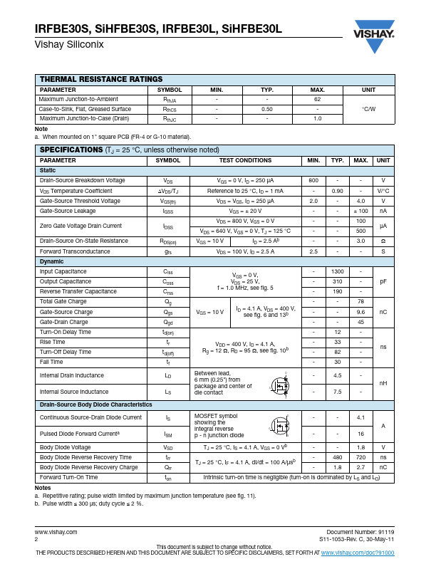
This document is subject to change without notice. THE PRODUCTS DESCRIBED HEREIN AND THIS DOCUMENT ARE SUBJECT TO SPECIFIC DISCLAIMERS, SET FORTH AT IRFBE30S, SiHFBE30S, IRFBE30L, SiHFBE30L Vishay Siliconix THERMAL RESISTANCE RATINGS PARAMETER SYMBOL Maximum Junction-to-Ambient RthJA Case-to-Sink, Flat, Greased Surface RthCS Maximum Junction-to-Case (Drain) RthJC Note a.IRFBE30L Specifications
- Package : TO-262-3
- Mount Type : Through Hole
- Current Rating : 4.1A
- Breakdown Voltage : 800V
- RDS(on) Max : 3Ω
- Input Capacitance : 1.3nF
- Terminals : 3
- Channels : 1
- Rise Time : 33ns
- Fall Time : 30ns
- Max Power Dissipation : 125W
- Max Operating Temp : 150°C
- Min Operating Temp : -55°C
Source:
Octopart
| Part No. | IRFBE30L |
|---|---|
| Datasheet | IRFBE30L Download |
| Manufacturer |  Vishay |
| Description | Power MOSFET |
| Buy | Stock & Price |
FEATURES
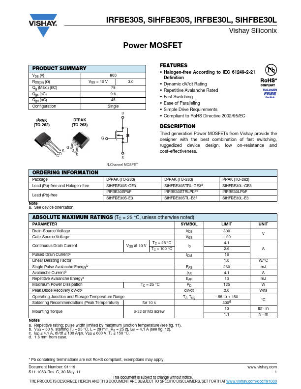
● Halogen-free According to IEC 61249-2-21 Definition● Dynamic dV/dt Rating
● Repetitive Avalanche Rated
● Fast Switching
● Ease of Paralleling
● Simple Drive Requirements
● Compliant to RoHS Directive 2002/95/EC
DESCRIPTION
Third generation Power MOSFETs from Vishay provide the designer with the best combination of fast switching, ruggedized device design, low on-resistance and cost-effectiveness. D2PAK (TO-263) SiHFBE30STRL-GE3a IRFBE30STRLPbFa SiHFBE30STL-E3a I2PAK (TO-262) SiHFBE30L-GE3 IRFBE30LPbF SiHFBE30L-E3ABSOLUTE MAXIMUM RATINGS
(TC = 25 °C, unless otherwise noted) PARAMETER SYMBOL Drain-Source Voltage Gate-Source Voltage Continuous Drain Current Pulsed Drain Currenta Linear Derating Factor Single Pulse Avalanche Energyb Avalanche Currenta Repetitive Avalanche Energya Maximum Power Dissipation Peak Diode Recovery dV/dtc VGS at 10 V TC = 25 °C TC = 100 °C TC = 25 °C VDS VGS ID IDM EAS IAR EAR PD dV/dt Operating Junction and Storage Temperature Range Soldering Recommendations (Peak Temperature) for 10 s TJ, Tstg Mounting Torque 6-32 or M3 screw Notes a.