Texas Instruments 54AC14
The 'AC14 contains six inverter gates each with a Schmitt trigger input. The 'AC14 contains six logic inverters which accept standard CMOS input signals and provide standard CMOS output levels.| Part No. | 54AC14 |
|---|---|
| Datasheet | 54AC14 Download |
| Manufacturer |  Texas Instruments |
| Description | Hex Inverter |
| Buy | Stock & Price |

FEATURES
1●23 ICC Reduced by 50%
● Outputs Source/Sink 24 mA
● Standard Military Drawing (SMD) – 54AC14: 5962-87624
● 54AC14 now Qualified to 300Krad RHA Designation, Refer to the SMD for More Information
DESCRIPTION
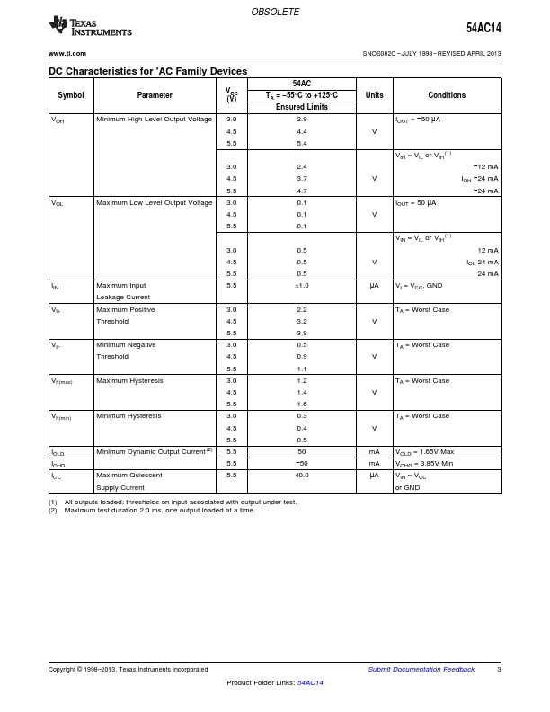
They are capable of transforming slowly changing input signals into sharply defined, jitter-free output signals. In addition, they have a greater noise margin than conventional inverters. The 'AC14 has hysteresis between the positive-going and negative-going input thresholds (typically 1.0V) which is determined internally by transistor ratios and is essentially insensitive to temperature and supply voltage variations. Logic Symbol Figure 1. IEEE/IEC Table 1. Function Table Input A L H Output O H L 1 Please be aware that an important notice concerning availability, standard warranty, and use in critical applications of Texas Instruments semiconductor products and disclaimers thereto appears at the end of this data sheet. FACT is a trademark of Fairchild Semiconductor. 2 All other trademarks are the property of their respective owners.