Texas Instruments 74ACT11643
The 74ACT11643 is characterized for operation from – 40°C to 85°C.| Part No. | 74ACT11643 |
|---|---|
| Datasheet | 74ACT11643 Download |
| Manufacturer |  Texas Instruments |
| Description | OCTAL BUS TRANSCEIVER |
| Buy | Stock & Price |
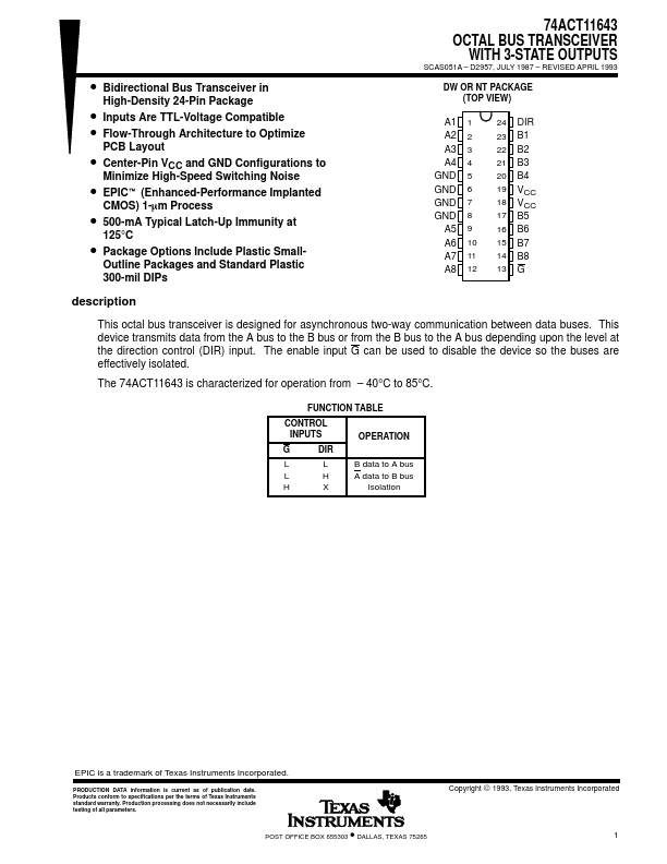
● Bidirectional Bus Transceiver in High-Density 24-Pin Package
● Inputs Are TTL-Voltage Compatible
● Flow-Through Architecture to Optimize PCB Layout
● Center-Pin VCC and GND Configurations to Minimize High-Speed Switching Noise t● EPIC (Enhanced-Performance Implanted CMOS) 1-mm Process
● 500-mA Typical Latch-Up Immunity at 125°C
● Package Options Include Plastic Small- Outline Packages and Standard Plastic 300-mil DIPs 74ACT11643 OCTAL BUS TRANSCEIVER WITH 3-STATE OUTPUTS SCAS051A – D2957, JULY 1987 – REVISED APRIL 1993 DW OR NT PACKAGE (TOP VIEW) A1 A2 A3 A4 GND GND GND GND A5 A6 A7 A8 1 2 3 4 5 6 7 8 9 10 11 12 24 DIR 23 B1 22 B2 21 B3 20 B4 19 VCC 18 VCC 17 B5 16 B6 15 B7 14 B8 13 G description This octal bus transceiver is designed for asynchronous two-way communication between data buses. This device transmits data from the A bus to the B bus or from the B bus to the A bus depending upon the level at the direction control (DIR) input. The enable input G can be used to disable the device so the buses are effectively isolated.