SN74ALVCH16524 Overview
Key Specifications
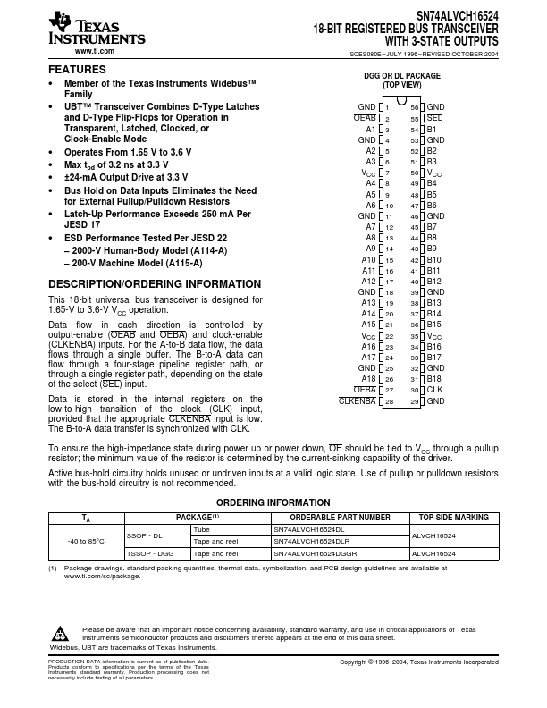
Package: SSOP
Mount Type: Surface Mount
Pins: 56
Max Voltage (typical range): 3.6 V
Key Features
- Member of the Texas Instruments Widebus™ Family
- UBT™ Transceiver Combines D-Type Latches and D-Type Flip-Flops for Operation in Transparent, Latched, Clocked, or Clock-Enable Mode
- Operates From 1.65 V to 3.6 V
- Max tpd of 3.2 ns at 3.3 V
- ±24-mA Output Drive at 3.3 V