onsemi J109
N-Channel JFET
| Part No. | J109 |
|---|---|
| Datasheet | J109 Download |
| Manufacturer |  onsemi |
| Description | N-Channel JFET |
| Buy | Stock & Price |
FEATURES
● This Device is Designed for Digital SwitchingAPPLICATIONS
where Very Low On Resistance is Mandatory● Sourced from Process 58
● These are Pb−Free Devices
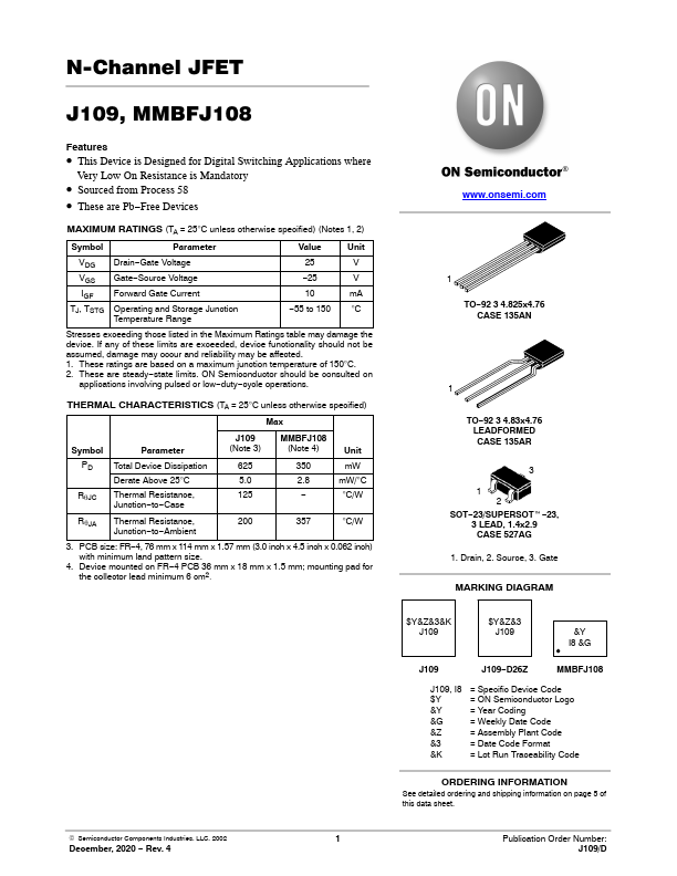
MAXIMUM RATINGS
(TA = 25°C unless otherwise specified) (Notes 1, 2) Symbol Parameter Value Unit VDG VGS IGF TJ, TSTG Drain−Gate Voltage Gate−Source Voltage Forward Gate Current Operating and Storage Junction Temperature Range 25 V −25 V 10 mA −55 to 150 °C Stresses exceeding those listed in theMAXIMUM RATINGS
table may damage the device. If any of these limits are exceeded, device functionality should not be assumed, damage may occur and reliability may be affected. 1. These ratings are based on a maximum junction temperature of 150°C. 2. These are steady−state limits. ON Semiconductor should be consulted on applications involving pulsed or low−duty−cycle operations. THERMAL CHARACTERISTICS (TA = 25°C unless otherwise specified) Max Symbol Parameter J109 (Note 3) MMBFJ108 (Note 4) Unit PD Total Device Dissipation 625 Derate Above 25°C 5.0 350 mW 2.8 mW/°C RqJC Thermal Resistance, 125 Junction−to−Case − °C/W RqJA Thermal Resistance, 200 357 °C/W Junction−to−Ambient 3.