FP1007R6
FP1007R6 is High current power inductors manufactured by EATON.
Technical Data 10007
Effective June 2017 Supersedes September 2012
High frequency, high current power inductors
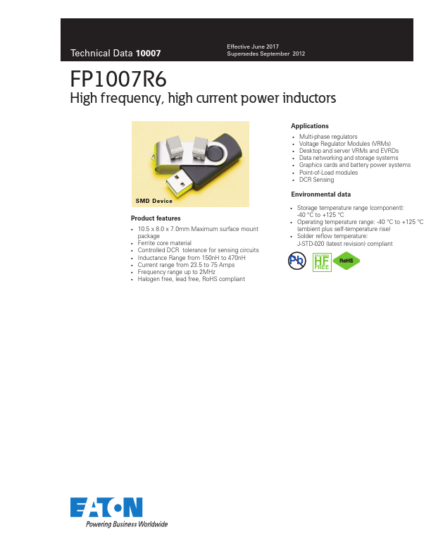
SMD Device
Product Features
- 10.5 x 8.0 x 7.0mm Maximum surface mount package
- Ferrite core material
- Controlled DCR tolerance for sensing circuits
- Inductance Range from 150nH to 470nH
- Current range from 23.5 to 75 Amps
- Frequency range up to 2MHz
- Halogen free, lead free, RoHS pliant
Applications
- Multi-phase regulators
- Voltage Regulator Modules (VRMs)
- Desktop and server VRMs and EVRDs
- Data networking and storage systems
- Graphics cards and battery power systems
- Point-of-Load modules
- DCR Sensing
Environmental data
- Storage temperature range...