Datasheet Summary
..
.fairchildsemi.
“Shoot-through” in Synchronous Buck Converters
Jon Klein Power Management Applications
Abstract
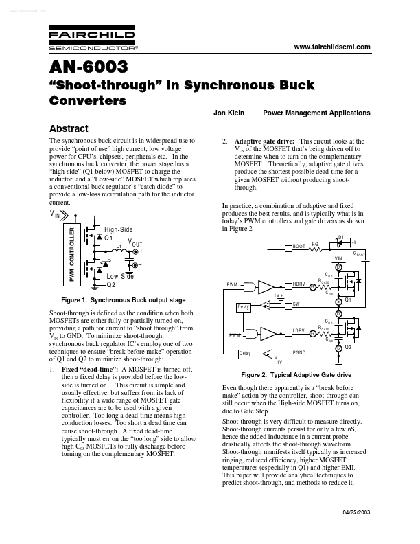
The synchronous buck circuit is in widespread use to provide “point of use” high current, low voltage power for CPU’s, chipsets, peripherals etc. In the synchronous buck converter, the power stage has a “high-side” (Q1 below) MOSFET to charge the inductor, and a “Low-side” MOSFET which replaces a conventional buck regulator’s “catch diode” to provide a low-loss recirculation path for the inductor current.
V IN
PWM CONTROLLER
2.
Adaptive gate drive: This circuit looks at the VGS of the MOSFET that’s being driven off to determine when to turn...