Datasheet Summary
Freescale Semiconductor Technical Data
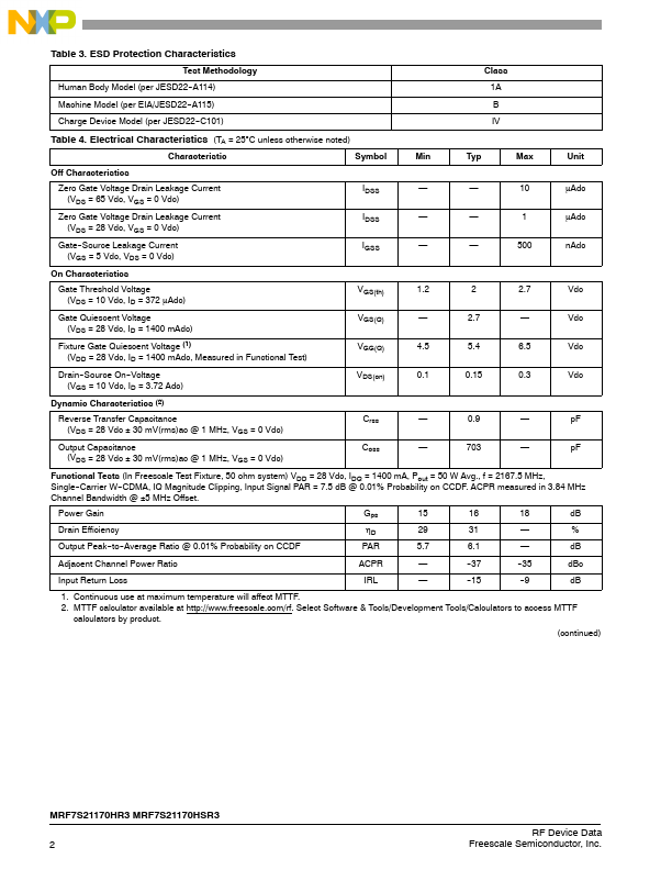
RF Power Field Effect Transistors
N--Channel Enhancement--Mode Lateral MOSFETs
Designed for CDMA base station applications with frequencies from 2110 to
2170 MHz. Suitable for CDMA and multicarrier amplifier applications. To be used in Class AB and Class C for PCN--PCS/cellular radio and WLL applications.
- Typical Single--Carrier W--CDMA
1C4h0a0nnmeAl ,BPanoudtw=id5t0h
Watts Avg., f = 3.84 MHz,
=Pe2r1fo6r7m.5anMcHe:z,VIDQDM=a2g8nVituodltes,CIDliQpp=ing, Input Signal PAR = 7.5 dB @ 0.01%
Probability on CCDF.
Power Gain
- 16 dB
Drain Efficiency
- 31%
Device Output Signal PAR
- 6.1 dB @ 0.01% Probability on CCDF
ACPR @ 5 MHz Offset
- --37...