IXFX220N15P Overview
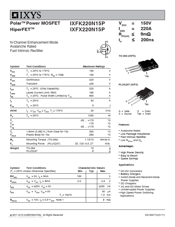
Key Features
- High Power Density Easy to Mount Space Savings
| Seller | Inventory | Price Breaks | Buy |
|---|---|---|---|
| UnikeyIC | 30000 | 10+ : 1.4054 USD 20+ : 1.3819 USD 30+ : 1.3467 USD |
View Offer |
| Unikeyic (ICkey) | 30000 | 10+ : 1.4054 USD 20+ : 1.3819 USD 30+ : 1.3467 USD |
View Offer |
| Part Number | Manufacturer | Description |
|---|---|---|
| IXFK24N90Q | IXYS | HiPerFET Power MOSFET |
| IXFV18N90PS | IXYS | Polar Power MOSFET HiPerFET |
| 98984 | IXYS | HiPerFET Power MOSFETs Q-Class |