• Part: IXGX35N120CD1
  • Description: HiPerFAST IGBT
  • Manufacturer: IXYS
  • Size: 154.58 KB
Download IXGX35N120CD1 Datasheet PDF
IXYS
IXGX35N120CD1
IXGX35N120CD1 is HiPerFAST IGBT manufactured by IXYS.
- Part of the IXGK35N120C comparator family.
Features C = Collector, TAB = Collector Md Weight Mounting torque (M3) (IXGK) 1.13/10Nm/lb.in. TO-264 AA PLUS247TM 10 6 g g International standard packages JEDEC TO-264 and PLUS247TM - 
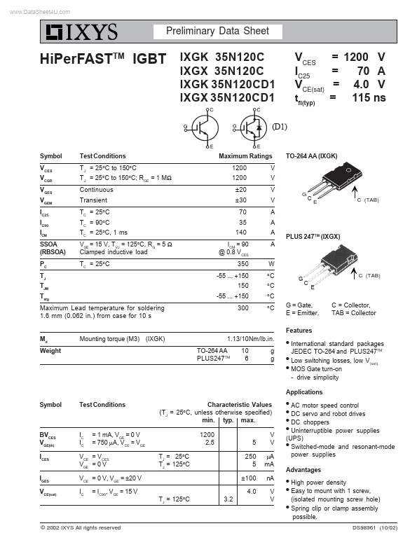
Low switching losses, low V(sat) - MOS Gate turn-on - drive simplicity - Applications Symbol Test Conditions Characteristic Values (TJ = 25°C, unless otherwise specified) min. typ. max. 1200 2.5 TJ = 25°C TJ = 125°C 5 250 5 ± 100 TJ = 125°C 4.0 3.2 V V µA m A n A V V AC motor speed control DC servo and robot drives - DC choppers - Uninterruptible power supplies (UPS) - Switched-mode and resonant-mode power supplies - - BVCES VGE(th) ICES IGES VCE(sat) IC IC = 1 m A, VGE = 0 V = 750 µA, VCE = VGE VCE = VCES VGE = 0 V VCE = 0 V, VGE = ±20 V IC = IC90, VGE = 15 V Advantages - - High power density Easy to mount with 1 screw, (isolated mounting screw hole) Spring clip or clamp assembly possible. DS98961 (10/02) - © 2002 IXYS All rights reserved IXGK 35N120C IXGX 35N120C Symbol Test Conditions Characteristic Values (TJ = 25°C, unless otherwise specified) min. typ. max. 30 40 4620 VCE = 25 V, VGE = 0 V, f = 1 MHz 260 90 170 IC = IC90, VGE = 15 V, VCE = 0.5 VCES 28 57 Inductive load, TJ = 25°C IC = IC90, VGE = 15 V VCE = 0.8 VCES, RG = Roff = 5 Ω Remarks: Switching times may increase for VCE (Clamp) > 0.8 - VCES, higher TJ or increased RG Inductive load, TJ = 125°C IC = IC90, VGE = 15 V VCE = 0.8 VCES, RG = Roff = 5 Ω Remarks: Switching times may increase for VCE (Clamp) > 0.8 - VCES, higher TJ or increased RG 50 27 150 115 3.0 55 31 2.6 220 260 6.2 220 190 S p F p F p F n C n C n C ns ns ns ns IXGK IXGX 35N120CD1 35N120CD1 TO-264 AA Outline (IXGK) gfs Cies Coes Cres Qg Qge Qgc td(on) tri td(off) tfi Eoff td(on) tri Eon td(off) tfi Eoff Rth JC Rth CK IC = IC90; VCE = 10 V, Pulse test, t ≤ 300 µs, duty cycle ≤ 2 % Dim. A A1 A2 b b1 b2 c D E e J K L L1 P Q Q1 R R1 S T Millimeter Min. Max. 4.82 5.13 2.54 2.89 2.00 2.10 1.12 1.42 2.39 2.69 2.90 3.09 0.53 0.83 25.91 26.16 19.81 19.96...