IRFR9024NCPBF Overview
(IRFR9024NCPbF) (IRFU9024NCPbF) Lead-Free PD - 96048 IRFR9024NCPbF IRFU9024NCPbF .irf. 1 05/31/06 IRFR/U9024NCPbF 2 .irf. 3 IRFR/U9024NCPbF 4 .irf.
| Part number | IRFR9024NCPBF |
|---|---|
| Datasheet | IRFR9024NCPBF Datasheet PDF (Download) |
| File Size | 1.32 MB |
| Manufacturer | International Rectifier (now Infineon) |
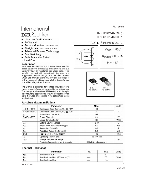
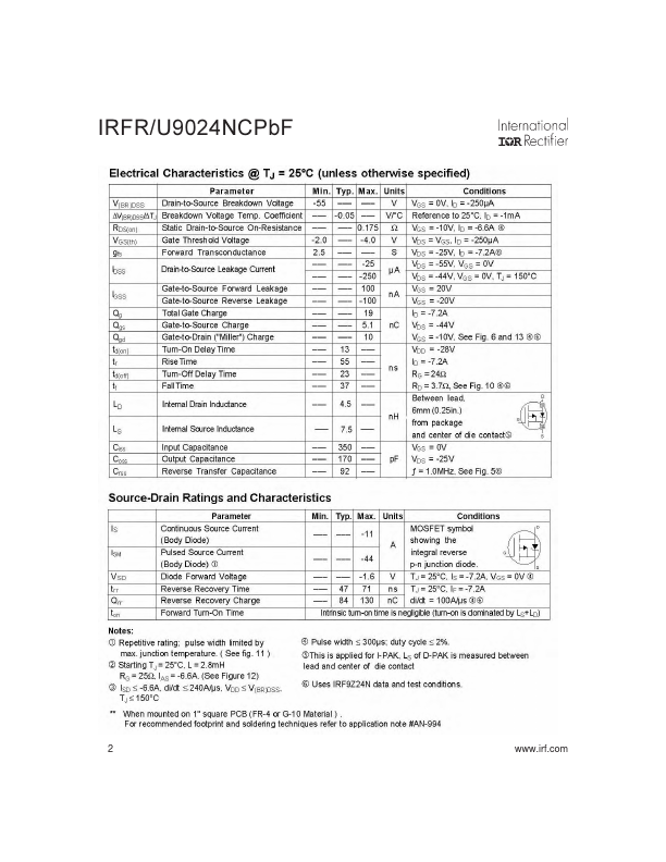
| Description | Power MOSFET |
|
|
(IRFR9024NCPbF) (IRFU9024NCPbF) Lead-Free PD - 96048 IRFR9024NCPbF IRFU9024NCPbF .irf. 1 05/31/06 IRFR/U9024NCPbF 2 .irf. 3 IRFR/U9024NCPbF 4 .irf.
| Brand Logo | Part Number | Description | Manufacturer |
|---|---|---|---|
| IRFR9024N | P-Channel MOSFET | INCHANGE | |
| IRFR9024N | P-Channel MOSFET | Kexin | |
| IRFR9024N | 60V P-Channel Enhancement Mode MOSFET | EVVOSEMI |