Datasheet4U Logo Datasheet4U.com

MRF5S21130S - The RF MOSFET Line RF Power Field Effect Transistor

Download the MRF5S21130S datasheet PDF. This datasheet also covers the MRF5S21130 variant, as both devices belong to the same the rf mosfet line rf power field effect transistor family and are provided as variant models within a single manufacturer datasheet.

Description

10 µF, 35 V Tantalum Capacitors 220 nF Chip Capacitors (1812) 6.8 pF 100B Chip Capacitors 0.1 pF 100B Chip Capacitor 0.5 pF 100B Chip Capacitor 220 µF, 63 V Electrolytic Capacitor, Radial 1 kW, 1/4 W Chip Resistors Value, P/N or DWG 293D1106X9035D 1812Y224KXA 100B6R8CW 100B0R1BW 100B0R5BW 13668221 M

Features

  • urce Ω 2.87.
  • j9.49 3.13.
  • j9.86 4.05.
  • j10.90 4.80.
  • j11.75 5.55.
  • j11.87 Zload Ω 1.51.
  • j2.97 1.52.
  • j2.54 1.59.
  • j2.68 1.62.
  • j2.70 1.54.
  • j3.13 Zsource = Test circuit impedance as measured from gate to ground. Zload = Test circuit impedance as measured from drain to ground. Input Matching Network Device Under Test Output Matching Network Z source.

📥 Download Datasheet

Note: The manufacturer provides a single datasheet file (MRF5S21130_Motorola.pdf) that lists specifications for multiple related part numbers.

Full PDF Text Transcription (Reference)

The following content is an automatically extracted verbatim text from the original manufacturer datasheet and is provided for reference purposes only.

View original datasheet text
www.DataSheet4U.com MOTOROLA SEMICONDUCTOR TECHNICAL DATA Order this document by MRF5S21130/D MRF5S21130 RF Power Field Effect Transistors MRF5S21130R3 N–Channel Enhancement–Mode Lateral MOSFETs MRF5S21130S Designed for W–CDMA base station applications at frequencies from 2110 MRF5S21130SR3 to 2170 MHz. Suitable for TDMA, CDMA and multicarrier amplifier applicaThe RF MOSFET Line t i o n s . To b e u s e d i n C l a s s A B f o r P C N – P C S / c e l l u l 
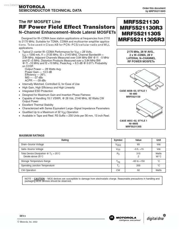
a r r a d i o a n d W L L applications. • Typical 2–carrier W–CDMA Performance for VDD = 28 Volts, IDQ = 1200 mA, f1 = 2135 MHz, f2 = 2145 MHz, Channel Bandwidth = 3.84 MHz, Adjacent Channels Measured over 3.84 MHz BW @ f1 –5 MHz and f2 +5 MHz, Distortion Products Measured over a 3.84 MHz BW @ f1 –10 MHz and f2 +10 MHz, Peak/Avg.
Published: |