MC10E112 Description
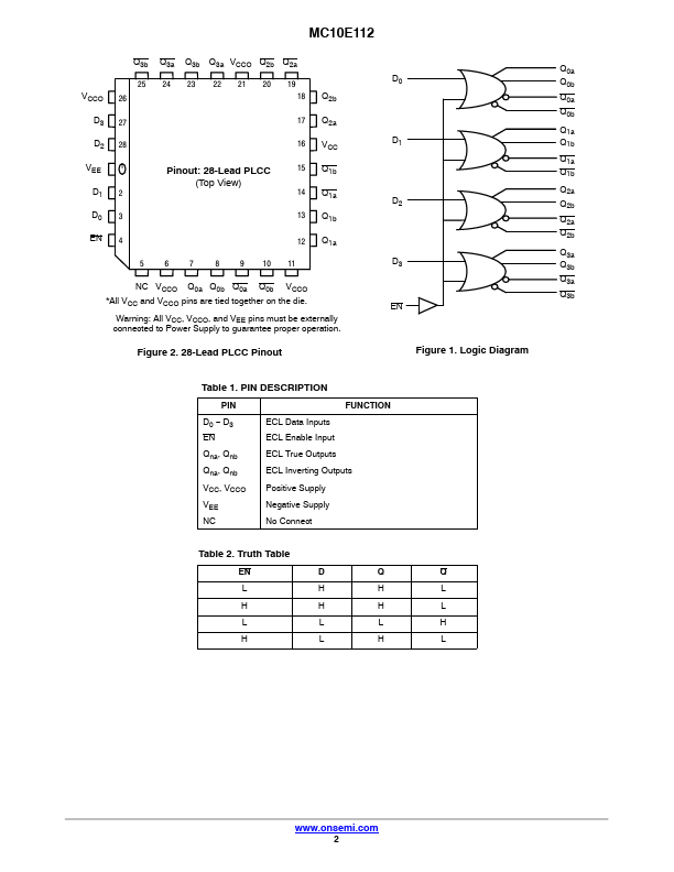
The MC10E112 is a quad driver with two pairs of OR/NOR outputs from each gate, and a mon, buffered enable input. Using the data inputs the device can serve as an ECL memory address fan-out driver. Using just the enable input, the device serves as a clock driver, although the MC10E/100E111 is designed specifically for this purpose, and offers lower skew than the E112.
MC10E112 Key Features
- 600 ps Max. Propagation Delay
- mon Enable Input
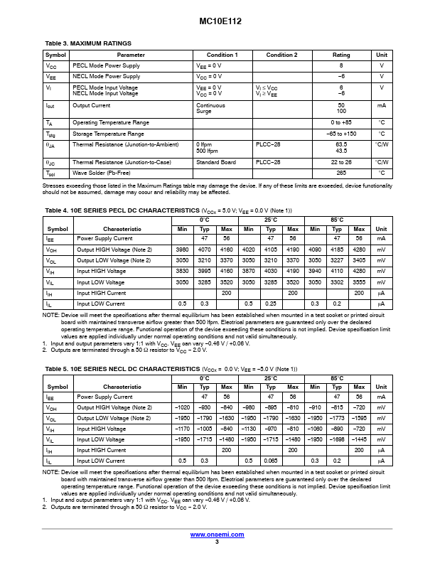
- PECL Mode Operating Range
- VCC = 4.2 V to 5.7 V with VEE = 0 V
- NECL Mode Operating Range
- VCC = 0 V with VEE = -4.2 V to -5.7 V
- Internal Input 50 kW Pulldown Resistors
- ESD Protection
- Human Body Model; > 2 kV
- Machine Model; > 200 V