G7SA-2A2B
G7SA-2A2B is Safety Relay manufactured by OMRON.
- Part of the G7SA comparator family.
- Part of the G7SA comparator family.
New Product
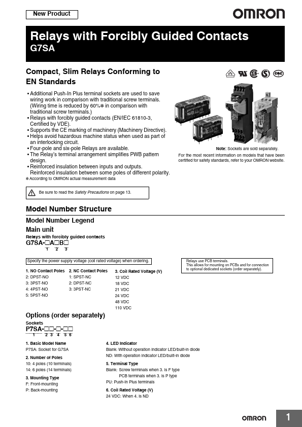
Relays with Forcibly Guided Contacts
G7SA pact, Slim Relays Conforming to EN Standards
- Additional Push-In Plus terminal sockets are used to save wiring work in parison with traditional screw terminals. (Wiring time is reduced by 60%- in parison with traditional screw terminals.)
- Relays with forcibly guided contacts (EN/IEC 61810-3, Certified by VDE).
- Supports the CE marking of machinery (Machinery Directive).
- Helps avoid hazardous machine status when used as part of an interlocking circuit.
- Four-pole and six-pole Relays are available.
- The Relay’s terminal arrangement simplifies PWB pattern design.
- Reinforced insulation between inputs and outputs.
Reinforced insulation between some poles of different polarity.
- According to OMRON actual measurement data
Note: Sockets are sold separately.
For the most recent information on models that have been certified for safety standards, refer to your OMRON website.
Be sure to read the Safety Precautions on page 13.
Model Number Structure
Model Number Legend Main unit
Relays with forcibly guided contacts
G7SA-@A@B@ ⎯1 ⎯2 ⎯3
Specify the power supply voltage (coil rated voltage) when ordering.
1. NO Contact Poles 2: DPST-NO 3: 3PST-NO 4: 4PST-NO 5: 5PST-NO
2. NC Contact Poles 1: SPST-NC 2: DPST-NC 3: 3PST-NC
Options (order separately)
Sockets
P7SA-@@-@-@@
⎯⎯1⎯⎯ ⎯2 ⎯3 ⎯4 ⎯5 ⎯6
3. Coil Rated Voltage (V) 12 VDC 18 VDC 21 VDC 24 VDC 48 VDC 110 VDC
Relays use PCB terminals. This allows for mounting on PCBs and for connection to optional dedicated sockets (order separately).
1. Basic Model Name P7SA: Socket for G7SA
2. Number of Poles 10: 4 poles (10 terminals) 14: 6 poles (14 terminals)
3. Mounting Type F: Front-mounting P: Back-mounting
4. LED Indicator Blank: Without operation indicator LED/built-in diode ND: With operation indicator LED/built-in diode
5. Terminal Type Blank: Screw terminals when 3. is F type
PCB terminals when 3. is P type PU: Push-In Plus terminals
6. Coil Rated Voltage (V)...