2SAR514PFRA Description
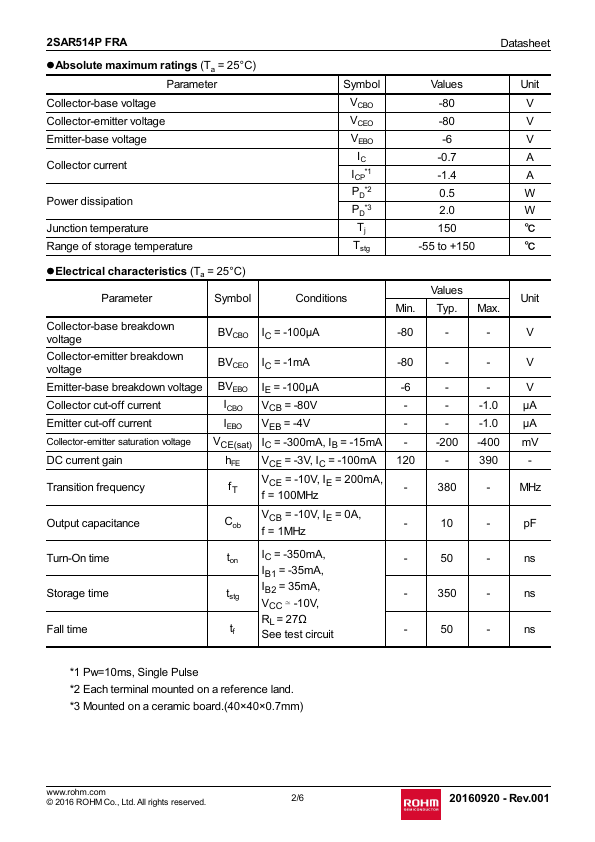
Package 2SAR514P FRA SOT-89 (MPT3) Package size Taping code Reel size (mm) Tape width (mm) Basic ordering unit.(pcs) Marking 4540 T100 180 12 1000 MD .rohm. -80 -80 -6 120 - - Values Typ. 3 Mounted on a ceramic board.(40×40×0.7mm) ns ns ns .rohm.
2SAR514PFRA Key Features
- Rev.001