TLP220GF
Overview
...
| Part | TLP220GF |
|---|---|
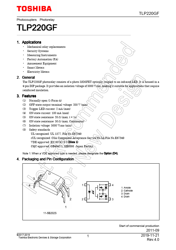
| Description | Photocoupler Photorelay |
| Category | Optocoupler |
| Manufacturer | Toshiba |
| Size | 220.73 KB |
...
| Part Number | Manufacturer | Description |
|---|---|---|
| TLP227GN | Toshiba | Photocoupler Photorelay |
| TLP227A | Toshiba | Photocoupler Photorelay |