Description
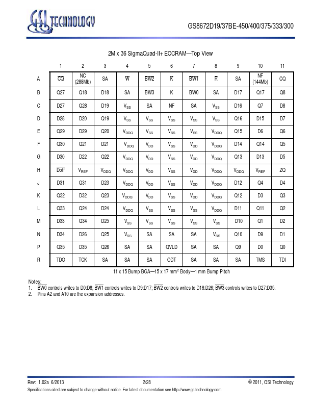
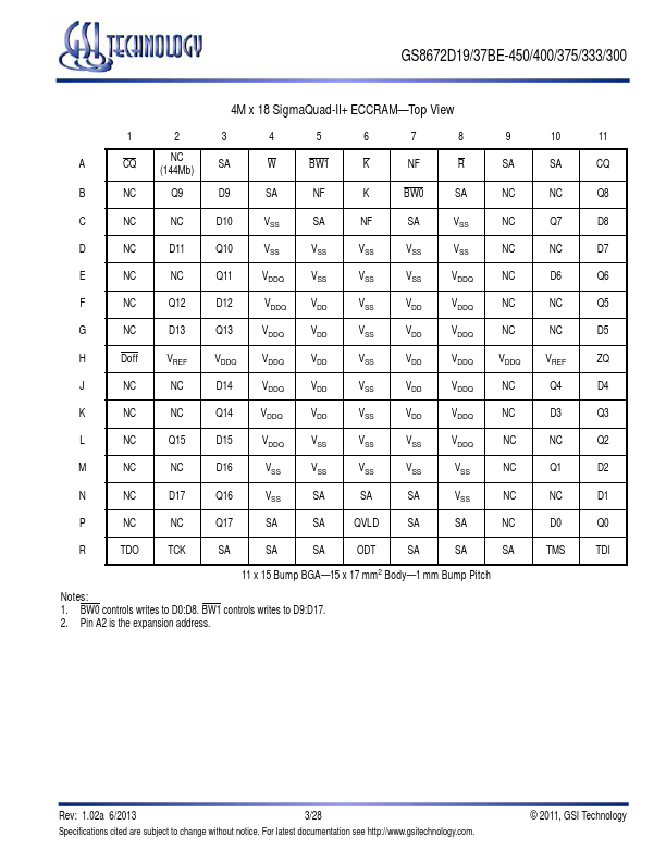
Table
Symbol
Description
Type Comments
SA
Synchronous Address Inputs
Input
R
Synchronous Read
Input Active Low
W
Synchronous Write
Input Active Low
BW0
BW3
Synchronous Byte Writes
Input Active Low
K
Input Clock
Input Active High
K
Input Clock
Input Active Low
TMS
Test Mode Select
Input
TDI
Test Data Input
Input
TCK
Test Clock Input
Input
TDO
Test Data Output
Output
VREF
HSTL Input Reference Voltage
Inp
Features
- 2.0 Clock Latency.
- On-Chip ECC with virtually zero SER.
- Simultaneous Read and Write SigmaQuad™ Interface.
- JEDEC-standard pinout and package.
- Dual Double Data Rate interface.
- Byte Write Capability due to ECC.
- Burst of 4 Read and Write.
- On-Die Termination (ODT) on Data (D), Byte Write (BW),
and Clock (K, K) outputs.
- 1.8 V +100/.
- 100 mV core power supply.
- 1.5 V HSTL Interface.
- Pipelined read o.
 GS8672D19BE-450-GSITechnology.pdf