• Part: G4000EF250
  • Description: Anode Shorted Gate Turn-Off Thyristor
  • Manufacturer: IXYS
  • Size: 0.98 MB
Download G4000EF250 Datasheet PDF
IXYS
G4000EF250
G4000EF250 is Anode Shorted Gate Turn-Off Thyristor manufactured by IXYS.
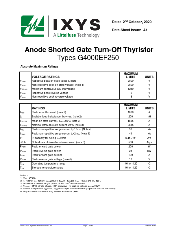
Date:- 2nd October, 2020 Data Sheet Issue:- A1 Anode Shorted Gate Turn-Off Thyristor Types G4000EF250 Absolute Maximum Ratings VDRM VRSM VDC-link VRRM VRSM VOLTAGE RATINGS Repetitive peak off-state voltage, (note 1) Non-repetitive peak off-state voltage, (note 1) Maximum continuous DC-link voltage Repetitive peak reverse voltage Non-repetitive peak reverse voltage MAXIMUM LIMITS 2500 2500 1250 18 18 UNITS V V V V V ITGQ Ls IT(AV)M IT(RMS) ITSM ITSM2 I2t di/dtcr PFGM PRGM IFGM VRGM Tj op Tstg RATINGS Peak turn-off current, (note 2) Snubber loop inductance, ITM=ITGQ, (note 2) Mean on-state current, Tsink=55°C (note 3) Nominal RMS on-state current, 25°C (note 3) Peak non-repetitive surge current tp=10ms, (Note 4) Peak non-repetitive surge current tp=2ms, (Note 4) I2t capacity for fusing tp=10ms Critical rate of rise of on-state current, (note 5) Peak forward gate power Peak reverse gate power Peak forward gate current Peak reverse gate voltage (note 6). Operating temperature range Storage temperature range Notes:1) VGK=-2Volts. 2) Tj=125°C, VD=1250V, VDM 2500V di GQ/dt=40A/µs, ITGQ=4000A and CS=6µF. 3) Double-side cooled, single phase; 50Hz, 180° half-sinewave. 4) Tj(initial)=125°C, single phase, 180° sinewave, re-applied voltage VD=VR≤10V. 5) IT=4000A repetitive, IGM=50A, di GM/dt=50A/µs. For di/dt>500A/µs please consult the factory. 6) May exceed this value during turn-off avalanche period. MAXIMUM LIMITS 4000 200 1835 3815 33 41 5.45×10⁶ 500 200 25 100 18 -40 to +125 -40 to +125 UNITS A n H A A k A k A A2s A/µs W k W A V °C °C Data Sheet. Type G4000EF250 Issue A1 Page 1 of 11 October 2020 Characteristics Anode Shorted Gate Turn-Off Thyristor type G4000EF250 VTM IL IH dv/dtcr IDRM IRRM IGKM IGT td tgt Eon tf ts tgq IGQM QGQ ttail Eoff Rth JK F Wt Parameter Maximum peak on-state voltage Latching current Holding current. Critical rate of rise of off-state voltage Peak off state current Peak reverse current Peak negative gate leakage current Gate...