STK6103
Overview
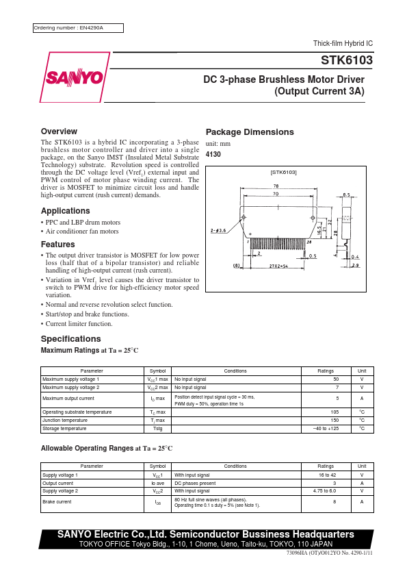
Package Dimensions
The STK6103 is a hybrid IC incorporating a 3-phase unit: mm brushless motor controller and driver into a single package, on the Sanyo IMST (Insulated Metal Substrate 4130 Technology) substrate. Revolution speed is controlled through the DC voltage level (Vref1) external input and PWM control of motor phase winding current. The driver is MOSFET to minimize circuit loss and handle high-output current (rush current) demands.
[STK6103]
Applications
- PPC and LBP drum motors
- Air conditioner fan motors
Features
- The output driver transistor is MOSFET for low power loss (half that of a bipolar transistor) and reliable handling of high-output current (rush current).
- Variation in Vref1 level causes the driver transistor to switch to PWM drive for high-efficiency motor speed variation.
- Normal and reverse revolution select function.
- Start/stop and brake functions.
- Current limiter function.
Specifications
Maximum Ratings at Ta = 25°C
Parameter Maximum...