Datasheet Details
| Part number | TB6552F |
|---|---|
| Manufacturer | Toshiba Semiconductor |
| File Size | 408.56 KB |
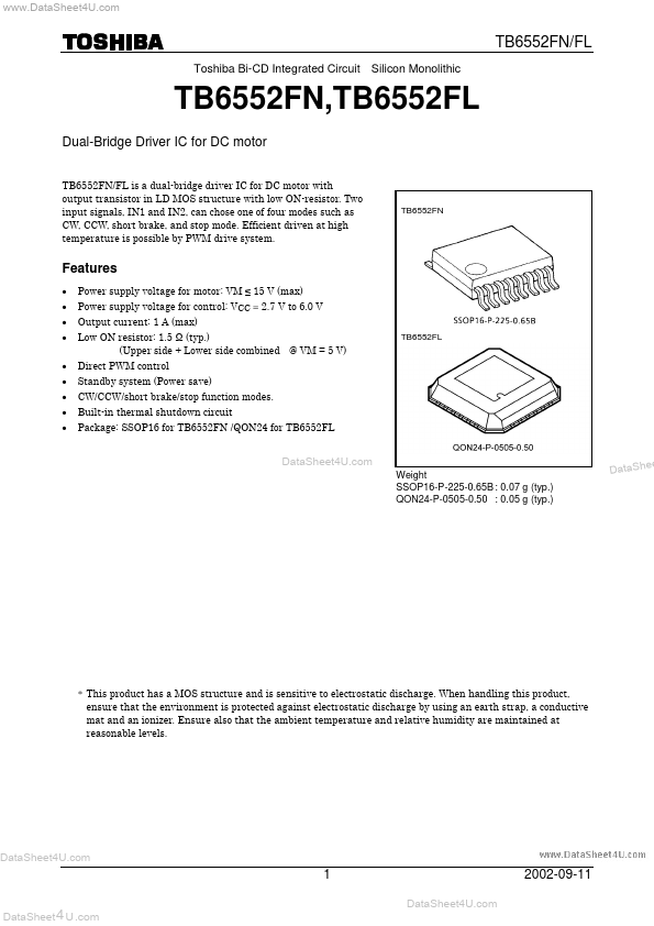
| Description | DUAL-BRIDGE DRIVER IC FOR DC MOTORS |
| Datasheet |
 TB6552F Datasheet TB6552F Datasheet
|
|
|
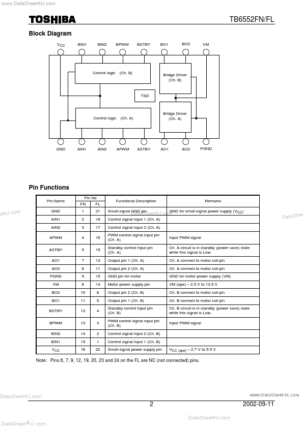
Control signal input 1 (Ch.
A) Control signal input 2 (Ch.
A) PWM control signal input pin (Ch.
| Part number | TB6552F |
|---|---|
| Manufacturer | Toshiba Semiconductor |
| File Size | 408.56 KB |
| Description | DUAL-BRIDGE DRIVER IC FOR DC MOTORS |
| Datasheet |
TB6552F Datasheet
|
|
|
|