Advanced Power Electronics AP28G40GEO
N-CHANNEL INSULATED GATE BIPOLAR TRANSISTOR
| Part No. | AP28G40GEO |
|---|---|
| Datasheet | AP28G40GEO Download |
| Manufacturer |  Advanced Power Electronics |
| Description | N-CHANNEL INSULATED GATE BIPOLAR TRANSISTOR |
| Buy | Stock & Price |
APPLICATIONS
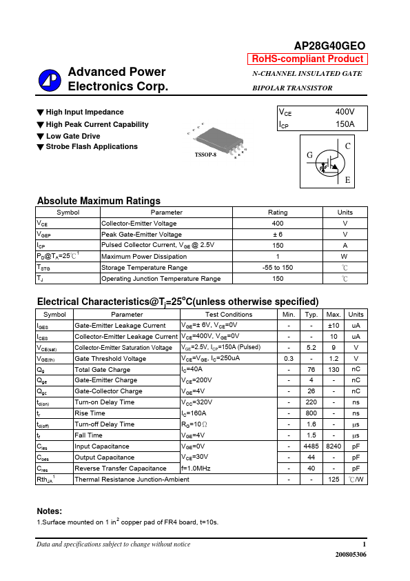
C C C C TSSOP-8 G E E E VCE ICP G 400V 150A C EABSOLUTE MAXIMUM RATINGS
Symbol Parameter VCE VGEP ICP PD@TA=25℃1 TSTG TJ Collector-Emitter Voltage Peak Gate-Emitter Voltage Pulsed Collector Current, VGE @ 2.5V Maximum Power Dissipation Storage Temperature Range Operating Junction Temperature Range Rating 400 ±6 150 1 -55 to 150 150 Units V V A W ℃ ℃ELECTRICAL CHARACTERISTICS
@Tj=25oC(unless otherwise specified) Symbol Parameter Test Conditions Min. Typ. IGES Gate-Emitter Leakage Current VGE=± 6V, VCE=0V -- ICES Collector-Emitter Leakage Current VCE=400V, VGE=0V -- VCE(sat) Collector-Emitter Saturation Voltage VGE=2.5V, ICP=150A (Pulsed) - 5.2 VGE(th) Gate Threshold Voltage VCE=VGE, IC=250uA 0.3 - Qg Total Gate Charge IC=40A - 76 Qge Gate-Emitter Charge VCE=200V -4 Qgc Gate-Collector Charge VGE=4V - 26 td(on) Turn-on Delay Time VCC=320V - 220 tr Rise Time IC=160A - 800 td(off) Turn-off Delay Time RG=10Ω - 1.6 tf Fall Time VGE=4V - 1.5 Cies Input Capacitance VGE=0V - 4485 C...