APT13GP120S
APT13GP120S is POWER MOS 7 IGBT manufactured by Advanced Power Technology.
- Part of the APT13GP120B comparator family.
- Part of the APT13GP120B comparator family.
TYPICAL PERFORMANCE CURVES ®
1200V APT13GP120B_S(G) APT13GP120B APT13GP120S APT13GP120BG- APT13GP120SG-
- G Denotes Ro HS pliant, Pb Free Terminal Finish.
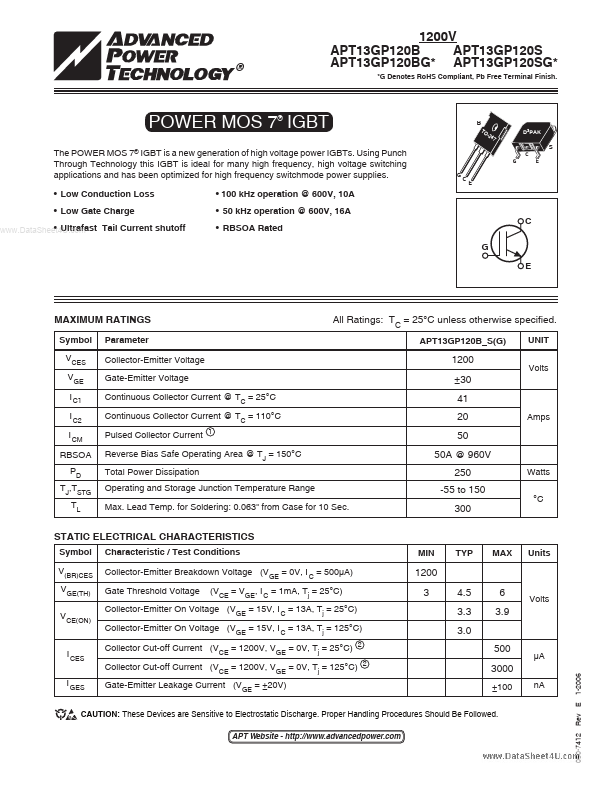
POWER MOS 7 IGBT
®
TO -2 47
D3PAK
The POWER MOS 7® IGBT is a new generation of high voltage power IGBTs. Using Punch Through Technology this IGBT is ideal for many high frequency, high voltage switching applications and has been optimized for high frequency switchmode power supplies.
- Low Conduction Loss
- Low Gate Charge
- Ultrafast Tail Current shutoff ..
- 100 k Hz operation @ 600V, 10A
- 50 k Hz operation @ 600V, 16A
- RBSOA Rated
MAXIMUM RATINGS
Symbol VCES VGE I C1 I C2 I CM RBSOA PD TJ,TSTG TL Parameter Collector-Emitter Voltage Gate-Emitter Voltage Continuous Collector Current @ TC = 25°C Continuous Collector Current @ TC = 110°C Pulsed Collector Current
All Ratings: TC = 25°C unless otherwise specified.
APT13GP120B_S(G) UNIT Volts
1200 ±30 41 20 50 50A @ 960V 250 -55 to 150 300
Amps
Reverse Bias Safe Operating Area @ TJ = 150°C Total Power Dissipation Operating and Storage Junction Temperature Range Max. Lead Temp. for Soldering: 0.063" from Case for 10 Sec.
Watts °C
STATIC ELECTRICAL CHARACTERISTICS
Symbol V(BR)CES VGE(TH) VCE(ON) Characteristic / Test Conditions Collector-Emitter Breakdown Voltage (VGE = 0V, I C = 500µA) Gate Threshold Voltage (VCE = VGE, I C = 1m A, Tj = 25°C) MIN TYP MAX Units
1200 3 4.5 3.3 3.0 500
2 2
6 3.9
Collector-Emitter On Voltage (VGE = 15V, I C = 13A, Tj = 25°C) Collector-Emitter On Voltage (VGE = 15V, I C = 13A, Tj = 125°C) Collector Cut-off Current (VCE = 1200V, VGE = 0V, Tj = 25°C)
Volts
I CES I GES
Gate-Emitter Leakage Current (VGE = ±20V)
±100 n A
CAUTION: These Devices are Sensitive to Electrostatic Discharge. Proper Handling Procedures Should Be Followed.
050-7412
APT Website
- http://.advancedpower.
Rev...